
ESP32-Based Smart Home Automation System with Gas Detection and Servo Control
View and Edit Project In Cirkit Designer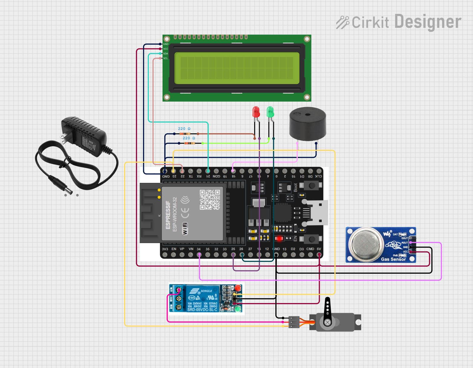
Circuit Documentation
Summary
This circuit involves an ESP32 microcontroller interfacing with various components including LEDs, a buzzer, a servo motor, an MQ6 gas sensor, a 5V relay, and a 16x2 I2C LCD. The ESP32 controls the LEDs, buzzer, and servo motor, reads data from the MQ6 gas sensor, and displays information on the LCD. The relay is used to control the power supply to the servo motor.
Component List
LED: Two Pin (green)
- Description: Green LED
- Pins: Cathode, Anode
LED: Two Pin (red)
- Description: Red LED
- Pins: Cathode, Anode
ESP32 38 PINS
- Description: ESP32 microcontroller with 38 pins
- Pins: GND, 23, 22/SCL, 1, 2, 21/SDA, 19, 18, 5, 17/TX2, 16/RX2, 4, 0, 15, D1, D0, CLK, 3V3, EN, VP, VN, 34, 35, 32, 33, 25, 26, 27, 14, 12, 13, D2, D3, 11, 5V/VIN
Servo
- Description: Servo motor
- Pins: GND, VCC, PWM
MQ6
- Description: Gas sensor
- Pins: VCC, GND, A0, DO
Resistor (220 Ohms)
- Description: Resistor with 220 Ohms resistance
- Pins: Pin1, Pin2
5V Relay
- Description: 5V relay module
- Pins: Normally Open, Common terminal, Normally Closed, In, GND, VCC
Buzzer
- Description: Buzzer
- Pins: PIN, GND
12V Power Supply
- Description: 12V power supply
- Pins: +, -
16x2 I2C LCD
- Description: 16x2 LCD with I2C interface
- Pins: GND, VCC, SDA, SCL
Wiring Details
LED: Two Pin (green)
- Cathode: Connected to Pin2 of a 220 Ohm resistor
- Anode: Connected to Pin 26 of the ESP32
LED: Two Pin (red)
- Cathode: Connected to Pin2 of a 220 Ohm resistor
- Anode: Connected to Pin 25 of the ESP32
ESP32 38 PINS
- GND: Connected to GND of the buzzer, GND of the 16x2 I2C LCD, GND of the 220 Ohm resistor, GND of the MQ6, GND of the servo, and GND of the 5V relay
- 18: Connected to PIN of the buzzer
- 26: Connected to Anode of the green LED
- 25: Connected to Anode of the red LED
- 5V/VIN: Connected to VCC of the MQ6, VCC of the 16x2 I2C LCD, and VCC of the 5V relay
- 34: Connected to A0 of the MQ6
- 23: Connected to PWM of the servo and In of the 5V relay
- 22/SCL: Connected to SCL of the 16x2 I2C LCD
- 21/SDA: Connected to SDA of the 16x2 I2C LCD
Servo
- GND: Connected to GND of the ESP32
- VCC: Connected to Normally Open of the 5V relay
- PWM: Connected to Pin 23 of the ESP32
MQ6
- VCC: Connected to 5V/VIN of the ESP32
- GND: Connected to GND of the ESP32
- A0: Connected to Pin 34 of the ESP32
Resistor (220 Ohms)
- Pin1: Connected to GND of the ESP32
- Pin2: Connected to Cathode of the green LED
- Pin1: Connected to GND of the ESP32
- Pin2: Connected to Cathode of the red LED
5V Relay
- VCC: Connected to 5V/VIN of the ESP32
- GND: Connected to GND of the ESP32
- In: Connected to Pin 23 of the ESP32
- Normally Open: Connected to VCC of the servo
Buzzer
- PIN: Connected to Pin 18 of the ESP32
- GND: Connected to GND of the ESP32
12V Power Supply
- +: Not connected in the provided net list
- -: Not connected in the provided net list
16x2 I2C LCD
- GND: Connected to GND of the ESP32
- VCC: Connected to 5V/VIN of the ESP32
- SDA: Connected to Pin 21/SDA of the ESP32
- SCL: Connected to Pin 22/SCL of the ESP32
Documented Code
sketch.ino
void setup() {
  // put your setup code here, to run once:

}

void loop() {
  // put your main code here, to run repeatedly:

}
documentation.txt