ESP32-Controlled AC LED Bulb with Voltage Monitoring
Circuit Documentation
Summary
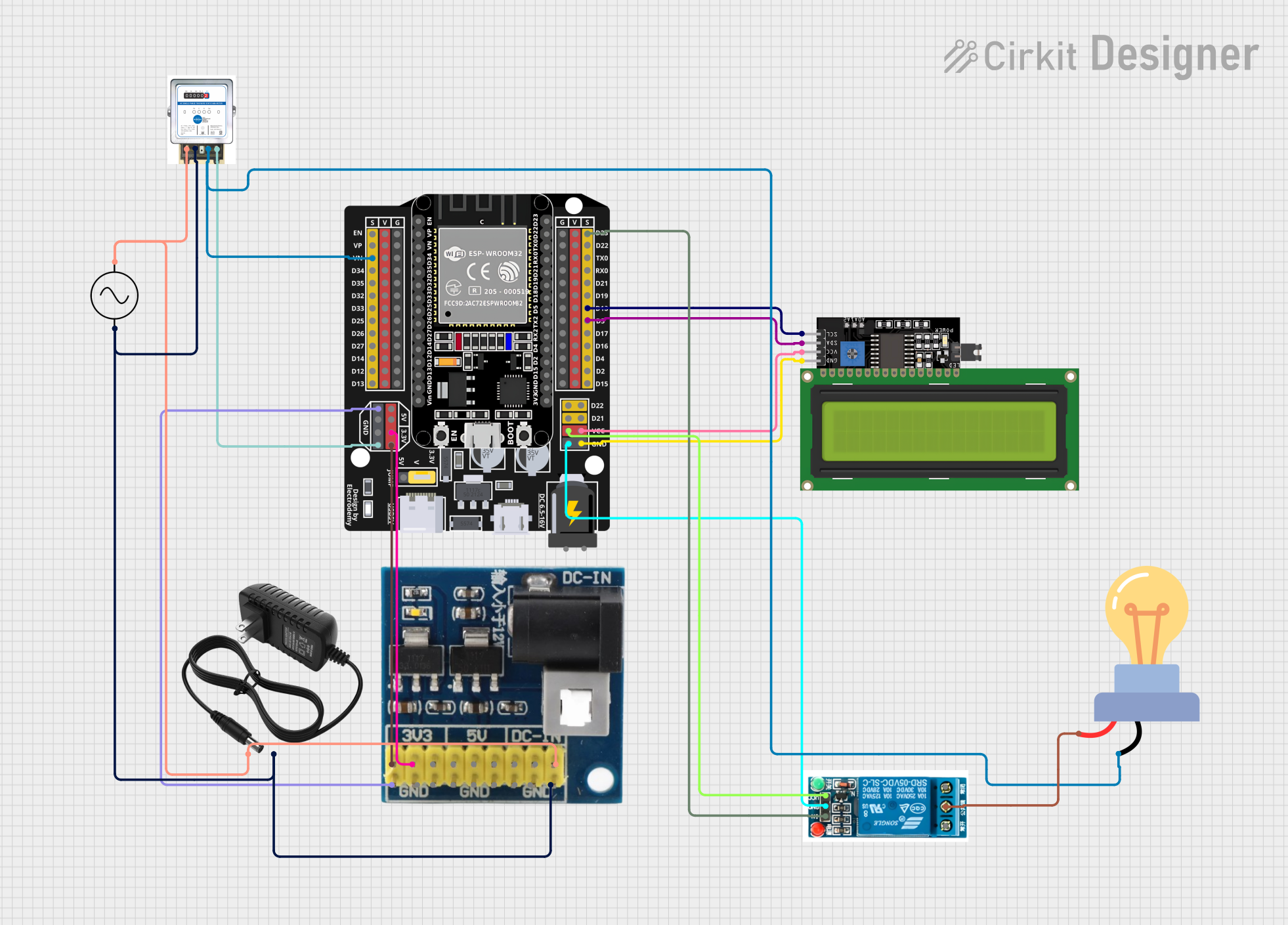
The circuit in question appears to be a power regulation and control system with an AC supply, a 12V power supply, and a voltage regulator to step down the voltage to 5V and 3V levels. It includes an ESP32 microcontroller for control purposes, an LCD display for user interface, a relay for controlling an AC load (LED bulb), and an analog meter for monitoring purposes. The ESP32 is interfaced with the LCD display via I2C communication and controls the relay which in turn controls the LED bulb. The voltage regulator provides the necessary power levels for the microcontroller and the LCD display.
Component List
Ac Supply
- Pins: +ve, -ve
- Description: Provides alternating current (AC) power to the circuit.
Analog Meter
- Pins: in +, IN -, Out +, Out -
- Description: Measures and displays the voltage or current passing through a point in the circuit.
12v Power Supply
- Pins: +, -
- Description: Provides a stable 12V DC output from an AC input.
Voltage Regulator 12v to 5v 3v
- Pins: gnd, dc in1, dc in2, dc in3, v6 5v, v5 5v, v4 5v, v3 3v, v2 3v, v1 3v
- Description: Steps down the voltage from 12V to 5V and 3V to power various components in the circuit.
LCD Display 16x4 I2C
- Pins: SCL, SDA, VCC, GND
- Description: A 16x4 character LCD display with an I2C interface for displaying information.
5v Relay
- Pins: Normally Open, Common terminal, Normally Closed, In, GND, VCC
- Description: An electromechanical switch used to control the LED bulb with the ESP32.
LED bulb AC / Bombillo AC
- Pins: +, -
- Description: An AC-powered LED bulb used as the load in the circuit.
ESP32 - Expansion Board
- Pins: +, -, EN, VP, VN, D34, D32, D33, D25, D26, D27, D14, D12, D13, D23, D22, TX0, RX0, D21, D19, D18, D5, D17, D16, D4, D2, D15, VCC, G, 5V, 3,3V, V
- Description: A microcontroller board with Wi-Fi and Bluetooth capabilities for controlling and monitoring the circuit.
Wiring Details
Ac Supply
- +ve: Connected to the + pin of the 12v power supply, in + pin of the Analog Meter, and dc in1 pin of the Voltage Regulator.
- -ve: Connected to the - pin of the 12v power supply, IN - pin of the Analog Meter, and gnd pin of the Voltage Regulator.
Analog Meter
- in +: See Ac Supply wiring.
- IN -: See Ac Supply wiring.
- Out +: Connected to the - pin of the LED bulb AC and VN pin of the ESP32 - Expansion Board.
- Out -: Connected to the G pin of the ESP32 - Expansion Board.
12v Power Supply
- +: See Ac Supply wiring.
- -: See Ac Supply wiring.
Voltage Regulator 12v to 5v 3v
- gnd: Connected to the -ve pin of the Ac Supply and G pin of the ESP32 - Expansion Board.
- dc in1: See Ac Supply wiring.
- v2 3v: Connected to the 3,3V pin of the ESP32 - Expansion Board.
- v1 3v: Connected to the 3,3V pin of the ESP32 - Expansion Board.
LCD Display 16x4 I2C
- SCL: Connected to the D18 pin of the ESP32 - Expansion Board.
- SDA: Connected to the D5 pin of the ESP32 - Expansion Board.
- VCC: Connected to the VCC pin of the ESP32 - Expansion Board.
- GND: Connected to the G pin of the ESP32 - Expansion Board.
5v Relay
- Common terminal: Connected to the + pin of the LED bulb AC.
- In: Connected to the D23 pin of the ESP32 - Expansion Board.
- GND: Connected to the G pin of the ESP32 - Expansion Board.
- VCC: Connected to the VCC pin of the ESP32 - Expansion Board.
LED bulb AC / Bombillo AC
- +: Connected to the Common terminal of the 5v relay.
- -: Connected to the Out + pin of the Analog Meter.
ESP32 - Expansion Board
- VN: See Analog Meter wiring.
- G: See Analog Meter and Voltage Regulator wiring.
- 3,3V: See Voltage Regulator wiring.
- D18: See LCD Display wiring.
- D5: See LCD Display wiring.
- VCC: See LCD Display and 5v Relay wiring.
- D23: See 5v Relay wiring.
Documented Code
No code has been provided for the microcontroller. The documentation of the code would include details on the initialization of peripherals, the main control loop, interrupt service routines, and any communication protocols used. Since the ESP32 is connected to an LCD display via I2C and controls a relay, the code would likely initialize the I2C peripheral, configure GPIO pins for relay control, and include functions to update the display and respond to external inputs or internal events.