
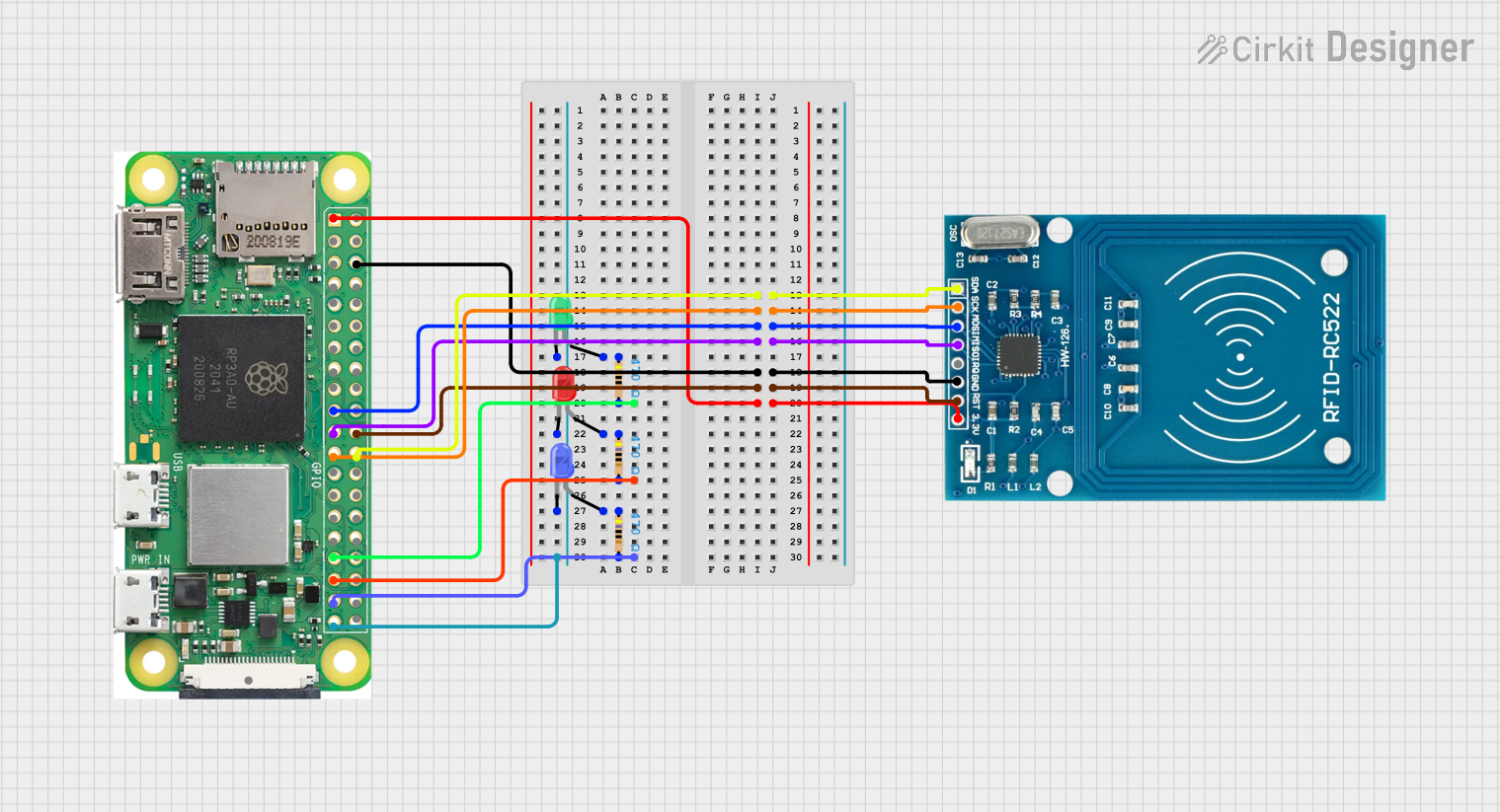
Circuit Documentation
Summary
This document provides a detailed overview of a circuit that integrates a Raspberry Pi Zero W, an RFID-RC522 module, and three LEDs (green, blue, and red) with associated resistors. The Raspberry Pi Zero W serves as the central controller, interfacing with the RFID module and controlling the LEDs.
Component List
Raspberry Pi Zero W
- Description: A small, affordable, and versatile single-board computer.
- Pins: 5V, 3V3, GPIO2 (SDA), GPIO 3, GROUND, GPIO 14, GPIO15, GPIO 18, GND, GPIO 23, GPIO24, GPIO 25, GPIO 8, GPIO 7, GPIO 1, GPIO 12, GPIO 16, GPIO 20, GPIO 21, GPIO 04, GPIO 17, GPIO 27, GPIO 22, GPIO 10, GPIO 9, GPIO 11, GPIO 0, GPIO 5, GPIO 6, GPIO 13, GPIO 19, GPIO 26, CSI (CAMERA)
RFID-RC522
- Description: A low-cost RFID module used for reading RFID tags.
- Pins: VCC (3.3V), RST, GND, IRQ, MISO, MOSI, SCK, SDA
LED: Two Pin (green)
- Description: A green LED with two pins.
- Pins: cathode, anode
LED: Two Pin (blue)
- Description: A blue LED with two pins.
- Pins: cathode, anode
LED: Two Pin (red)
- Description: A red LED with two pins.
- Pins: cathode, anode
Resistor (470 Ohms)
- Description: A resistor with a resistance of 470 Ohms.
- Pins: pin1, pin2
Wiring Details
Raspberry Pi Zero W
- GPIO 8 is connected to SDA of the RFID-RC522.
- GPIO 11 is connected to SCK of the RFID-RC522.
- GPIO 10 is connected to MOSI of the RFID-RC522.
- GPIO 9 is connected to MISO of the RFID-RC522.
- GROUND is connected to GND of the RFID-RC522.
- GPIO 25 is connected to RST of the RFID-RC522.
- GPIO 13 is connected to pin2 of a Resistor (470 Ohms).
- 3V3 is connected to VCC (3.3V) of the RFID-RC522.
- GPIO 19 is connected to pin2 of a Resistor (470 Ohms).
- GPIO 26 is connected to pin2 of a Resistor (470 Ohms).
- GND is connected to the cathode of the green LED, blue LED, and red LED.
RFID-RC522
- SDA is connected to GPIO 8 of the Raspberry Pi Zero W.
- SCK is connected to GPIO 11 of the Raspberry Pi Zero W.
- MOSI is connected to GPIO 10 of the Raspberry Pi Zero W.
- MISO is connected to GPIO 9 of the Raspberry Pi Zero W.
- GND is connected to GROUND of the Raspberry Pi Zero W.
- RST is connected to GPIO 25 of the Raspberry Pi Zero W.
- VCC (3.3V) is connected to 3V3 of the Raspberry Pi Zero W.
LED: Two Pin (green)
- cathode is connected to GND of the Raspberry Pi Zero W.
- anode is connected to pin1 of a Resistor (470 Ohms).
LED: Two Pin (blue)
- cathode is connected to GND of the Raspberry Pi Zero W.
- anode is connected to pin1 of a Resistor (470 Ohms).
LED: Two Pin (red)
- cathode is connected to GND of the Raspberry Pi Zero W.
- anode is connected to pin1 of a Resistor (470 Ohms).
Resistor (470 Ohms)
- pin2 of the first resistor is connected to GPIO 13 of the Raspberry Pi Zero W.
- pin2 of the second resistor is connected to GPIO 19 of the Raspberry Pi Zero W.
- pin2 of the third resistor is connected to GPIO 26 of the Raspberry Pi Zero W.
- pin1 of the first resistor is connected to the anode of the green LED.
- pin1 of the second resistor is connected to the anode of the blue LED.
- pin1 of the third resistor is connected to the anode of the red LED.
Code
No code is provided for this circuit.