
Battery-Powered IR Sensor and AND Gate Circuit with LED Indicator
View and Edit Project In Cirkit Designer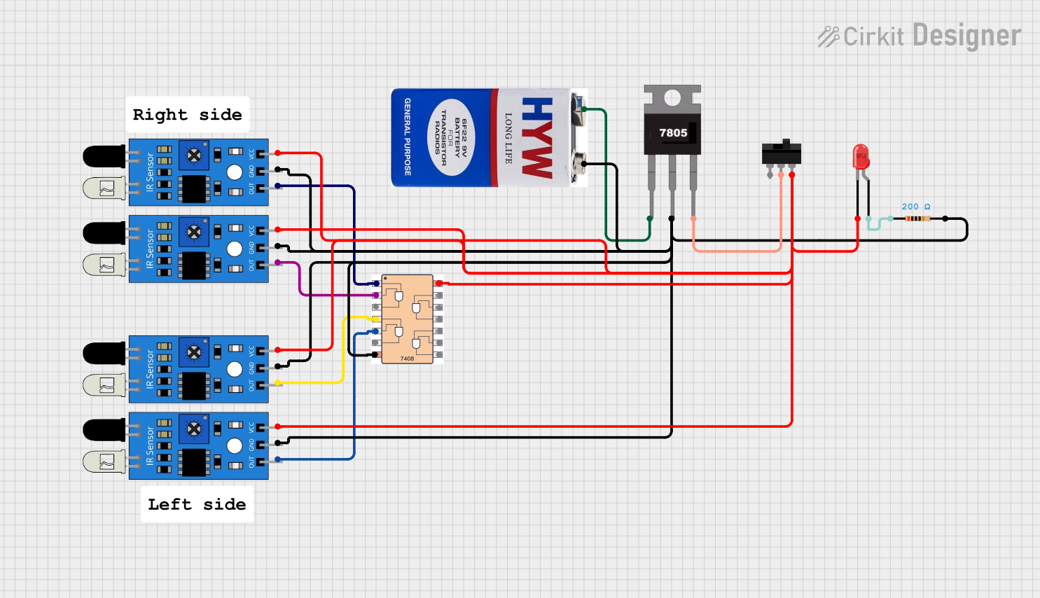
Circuit Documentation
Summary
This circuit is designed to utilize multiple IR sensors and a 7408 AND gate IC to control an LED. The circuit is powered by a 9V battery regulated to 5V using a 7805 voltage regulator. A toggle switch is used to control the power to the circuit. The IR sensors detect objects and their outputs are fed into the 7408 AND gate. The output of the AND gate is used to control the LED through a resistor.
Component List
7408 AND Gate IC
- Description: Quad 2-input AND gate
- Pins: 14 (2, 1, 3, 4, 5, 6, Gnd, Vcc, 8, 9, 10, 11, 12, 13)
IR Sensor
- Description: Infrared sensor for object detection
- Pins: 3 (out, gnd, vcc)
9V Battery
- Description: Power source
- Pins: 2 (+, -)
LED: Two Pin (red)
- Description: Light Emitting Diode
- Pins: 2 (cathode, anode)
7805 Voltage Regulator
- Description: 5V voltage regulator
- Pins: 3 (Vin, Gnd, Vout)
Toggle Switch
- Description: Switch to control power
- Pins: 3 (L1, COM, L2)
Resistor
- Description: 200 Ohms resistor
- Pins: 2 (pin1, pin2)
Wiring Details
7408 AND Gate IC
- Pin 2: Connected to the
outpin of the first IR sensor. - Pin 1: Connected to the
outpin of the second IR sensor. - Pin 3: Output of the AND gate (not connected in this circuit).
- Pin 4: Connected to the
outpin of the third IR sensor. - Pin 5: Connected to the
outpin of the fourth IR sensor. - Pin 6: Output of the AND gate (not connected in this circuit).
- Pin Gnd: Connected to the ground net.
- Pin Vcc: Connected to the Vcc net.
IR Sensor 1
- out: Connected to Pin 2 of the 7408 AND gate.
- gnd: Connected to the ground net.
- vcc: Connected to the Vcc net.
IR Sensor 2
- out: Connected to Pin 1 of the 7408 AND gate.
- gnd: Connected to the ground net.
- vcc: Connected to the Vcc net.
IR Sensor 3
- out: Connected to Pin 4 of the 7408 AND gate.
- gnd: Connected to the ground net.
- vcc: Connected to the Vcc net.
IR Sensor 4
- out: Connected to Pin 5 of the 7408 AND gate.
- gnd: Connected to the ground net.
- vcc: Connected to the Vcc net.
9V Battery
- +: Connected to the Vin pin of the 7805 voltage regulator.
- -: Connected to the ground net.
LED: Two Pin (red)
- cathode: Connected to the Vcc net.
- anode: Connected to pin1 of the resistor.
7805 Voltage Regulator
- Vin: Connected to the + pin of the 9V battery.
- Gnd: Connected to the ground net.
- Vout: Connected to the COM pin of the toggle switch.
Toggle Switch
- L2: Connected to the Vcc net.
- COM: Connected to the Vout pin of the 7805 voltage regulator.
- L1: Not connected.
Resistor
- pin1: Connected to the anode of the LED.
- pin2: Connected to the ground net.
Code
No microcontroller code is present in this circuit.