ESP32-Controlled Ultrasonic Sensors and Servo with Keypad Interface
Circuit Documentation
Summary
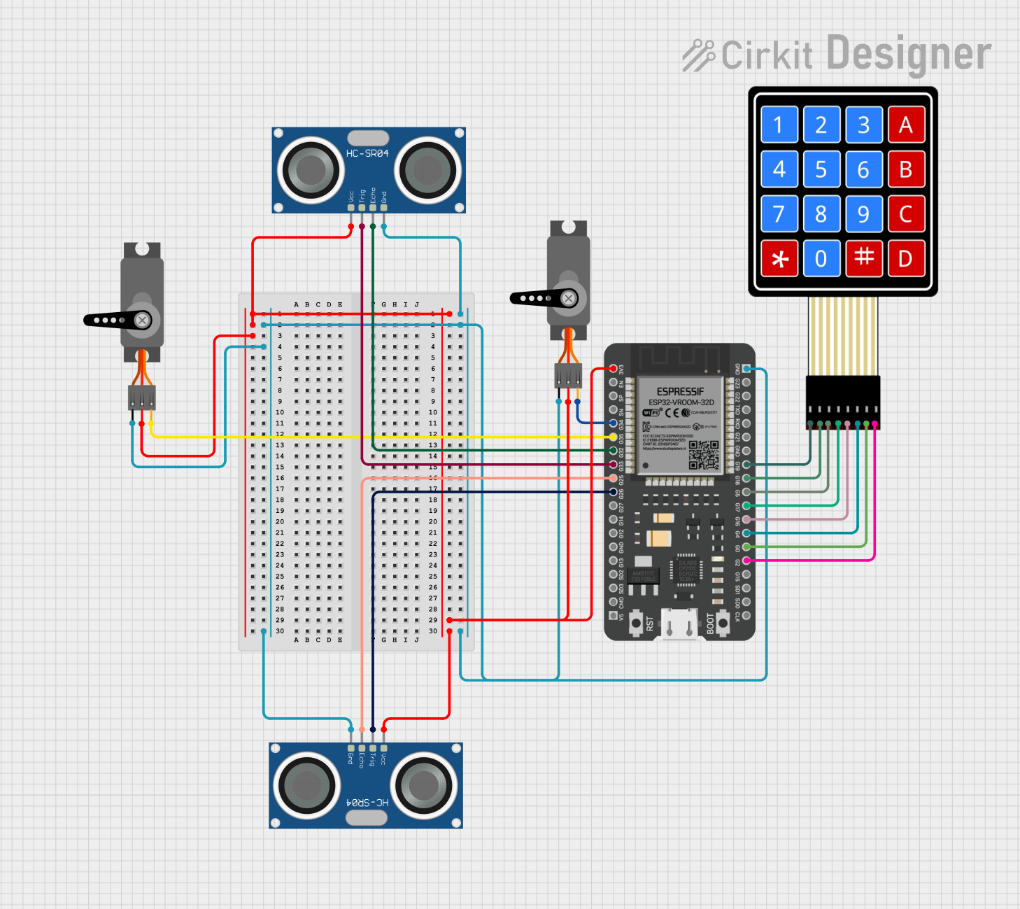
The circuit in question is designed to interface a microcontroller with a set of sensors and input devices. The core of the circuit is an ESP32 microcontroller, which is responsible for controlling two servo motors and interfacing with two HC-SR04 ultrasonic sensors and a 4x4 membrane matrix keypad. The ESP32 provides power to the sensors and servos and processes input signals from the ultrasonic sensors and the keypad. The servos are controlled via PWM signals, and the ultrasonic sensors are used for distance measurement. The keypad allows for user input to control the behavior of the system.
Component List
ESP32 - 38 pins
- Description: A powerful microcontroller with Wi-Fi and Bluetooth capabilities, featuring a wide range of GPIO pins for interfacing with various peripherals.
- Pins: 3V3, EN, SP, SN, G34, G35, G32, G33, G25, G26, G27, G14, G12, GND, G13, SD2, SD3, CMD, 5V, G23, G22, TXD, RXD, G21, G19, G18, G5, G17, G16, G4, G0, G2, G15, SD1, SD0, CLK
Servo
- Description: An actuator capable of precise angular positioning, controlled by a PWM signal.
- Pins: GND, VCC, PWM
HC-SR04 Ultrasonic Sensor
- Description: A sensor used for measuring distances via ultrasonic sound waves, consisting of a trigger and echo pin.
- Pins: VCC, TRIG, ECHO, GND
4X4 Membrane Matrix Keypad
- Description: An input device with 16 buttons arranged in a 4x4 grid, allowing for user interaction.
- Pins: R1, R2, R3, R4, C1, C2, C3, C4
Wiring Details
ESP32 - 38 pins
- 3V3: Connected to VCC of both HC-SR04 Ultrasonic Sensors and both Servos
- GND: Connected to GND of both HC-SR04 Ultrasonic Sensors and both Servos
- G35: Connected to PWM of one Servo
- G34: Connected to PWM of the other Servo
- G33: Connected to TRIG of one HC-SR04 Ultrasonic Sensor
- G32: Connected to ECHO of one HC-SR04 Ultrasonic Sensor
- G26: Connected to TRIG of the other HC-SR04 Ultrasonic Sensor
- G25: Connected to ECHO of the other HC-SR04 Ultrasonic Sensor
- G19, G18, G5, G17: Connected to R1, R2, R3, R4 of the 4X4 Membrane Matrix Keypad respectively
- G16, G4, G0, G2: Connected to C1, C2, C3, C4 of the 4X4 Membrane Matrix Keypad respectively
Servo
- VCC: Connected to 3V3 of ESP32
- GND: Connected to GND of ESP32
- PWM: Connected to either G35 or G34 of ESP32 (one servo to each)
HC-SR04 Ultrasonic Sensor
- VCC: Connected to 3V3 of ESP32
- GND: Connected to GND of ESP32
- TRIG: Connected to either G33 or G26 of ESP32 (one sensor to each)
- ECHO: Connected to either G32 or G25 of ESP32 (one sensor to each)
4X4 Membrane Matrix Keypad
- R1, R2, R3, R4: Connected to G19, G18, G5, G17 of ESP32 respectively
- C1, C2, C3, C4: Connected to G16, G4, G0, G2 of ESP32 respectively
Documented Code
There is no code provided for the microcontroller. The documentation of the code would typically include a description of the functionality, setup, and main loop, along with any interrupt service routines or additional functions. Since no code is available, this section cannot be completed. If code becomes available, it should be documented here with comments explaining the purpose and functionality of each section of the code.