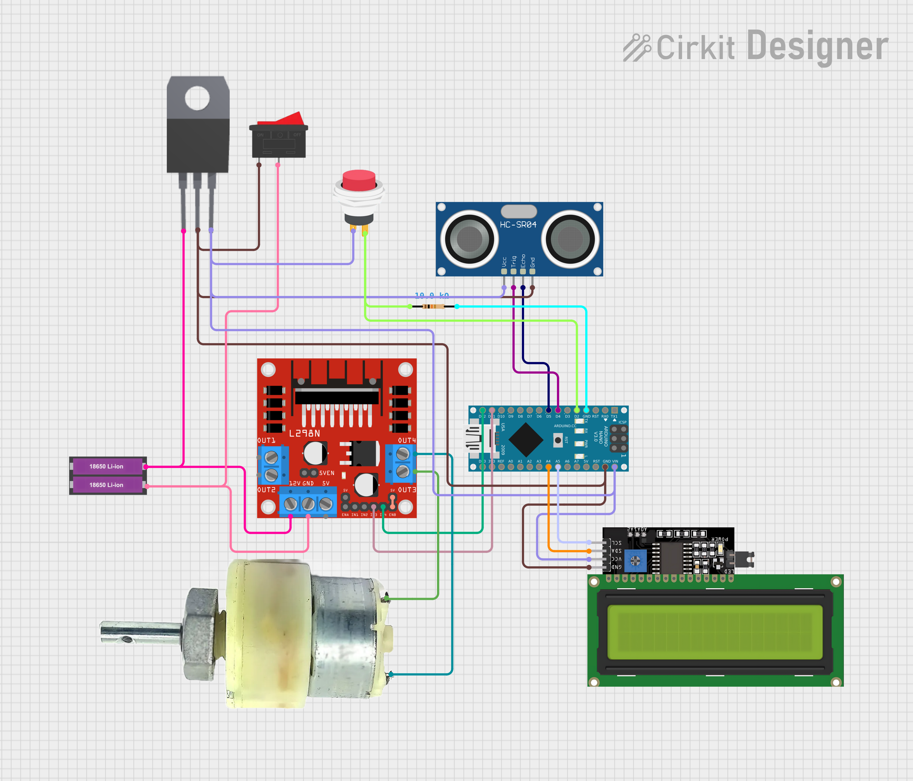
Arduino Nano-Controlled Robotic Vehicle with Ultrasonic Navigation and LCD Feedback

Circuit Documentation
Summary
This document provides a detailed overview of a circuit that includes an Arduino Nano as the central microcontroller, interfaced with various components such as an L298N DC motor driver, an LCD Display with I2C interface, switches, an ultrasonic sensor, a voltage regulator, a geared motor, and a power source consisting of two 18650 Li-ion batteries. The circuit is designed to control a motor, read distances using the ultrasonic sensor, and display information on the LCD screen. The Arduino Nano is programmed to manage these interactions.
Component List
Arduino Nano
- Microcontroller board based on the ATmega328P
- It has a variety of digital and analog I/O pins.
L298N DC Motor Driver
- Module for controlling up to two DC motors with a maximum current of 2A per channel.
- It provides an external power supply for motors and has pins for motor direction and speed control.
LCD Display 16x4 I2C
- A 16x4 character LCD display with an I2C interface for displaying data.
- Requires VCC and GND for power and SCL, SDA for I2C communication.
Rocker Switch
- A simple on-off switch to control the power flow in the circuit.
2Pin Push Switch
- A momentary push button switch used to trigger an action when pressed.
12V Geared Motor
- A motor with a gearbox to reduce speed and increase torque.
- Has two terminals for power connection.
HC-SR04 Ultrasonic Sensor
- A sensor for measuring distance using ultrasonic waves.
- It has pins for VCC, GND, TRIG (trigger), and ECHO (echo).
7808 Voltage Regulator
- A voltage regulator that outputs a constant 8V from a higher voltage input.
- Has pins for INPUT, GND, and OUTPUT.
18650 Li-ion Battery x 2
- A power source consisting of two 18650 Li-ion batteries.
- Provides a nominal voltage of 3.7V each, used in series or parallel configurations.
Resistor (10k Ohms)
- A passive component used to limit current or divide voltages in the circuit.
Wiring Details
Arduino Nano
- GND connected to the GND of the circuit.
- D2 connected to the 2Pin Push Switch and a 10k Ohm Resistor.
- D4 connected to the TRIG pin of the HC-SR04 Ultrasonic Sensor.
- D5 connected to the ECHO pin of the HC-SR04 Ultrasonic Sensor.
- D11/MOSI connected to the IN3 pin of the L298N Motor Driver.
- D12/MISO connected to the IN4 pin of the L298N Motor Driver.
- VIN connected to the VCC of the LCD Display, 7808 Voltage Regulator, and HC-SR04 Ultrasonic Sensor.
- A5 connected to the SCL pin of the LCD Display.
- A4 connected to the SDA pin of the LCD Display.
L298N DC Motor Driver
- OUT3 and OUT4 connected to the terminals of the 12V Geared Motor.
- 12V connected to the + terminal of the 18650 Li-ion Battery x 2.
- GND connected to the - terminal of the 18650 Li-ion Battery x 2 and the GND of the circuit.
- IN3 and IN4 connected to the D11/MOSI and D12/MISO pins of the Arduino Nano, respectively.
- ENB connected to +5V-J2 for enabling the motor driver.
LCD Display 16x4 I2C
- VCC connected to the VIN of the Arduino Nano.
- GND connected to the GND of the circuit.
- SCL connected to the A5 pin of the Arduino Nano.
- SDA connected to the A4 pin of the Arduino Nano.
Rocker Switch
- One side connected to the GND of the circuit.
2Pin Push Switch
- Input + connected to the VIN of the Arduino Nano.
- Output + connected to the D2 pin of the Arduino Nano and a 10k Ohm Resistor.
12V Geared Motor
- Terminal 1 connected to the OUT4 of the L298N Motor Driver.
- Terminal 2 connected to the OUT3 of the L298N Motor Driver.
HC-SR04 Ultrasonic Sensor
- VCC connected to the VIN of the Arduino Nano.
- TRIG connected to the D4 pin of the Arduino Nano.
- ECHO connected to the D5 pin of the Arduino Nano.
- GND connected to the GND of the circuit.
7808 Voltage Regulator
- INPUT connected to the + terminal of the 18650 Li-ion Battery x 2.
- GND connected to the GND of the circuit.
- OUTPUT connected to the VIN of the Arduino Nano.
18650 Li-ion Battery x 2
- terminal connected to the 12V of the L298N Motor Driver and INPUT of the 7808 Voltage Regulator.
- terminal connected to the GND of the circuit and the Rocker Switch.
Resistor (10k Ohms)
- One pin connected to the GND of the circuit.
- The other pin connected to the D2 pin of the Arduino Nano and the Output + of the 2Pin Push Switch.
Documented Code
sketch.ino
void setup() {
  // put your setup code here, to run once:

}

void loop() {
  // put your main code here, to run repeatedly:

}
documentation.txt
The code for the Arduino Nano is currently empty. The setup() function is intended for initialization code that runs once at the start, and the loop() function is for code that runs continuously. Additional code should be added to control the motor via the L298N driver, read distance measurements from the HC-SR04 sensor, and display data on the LCD screen.