
Circuit Documentation
Summary
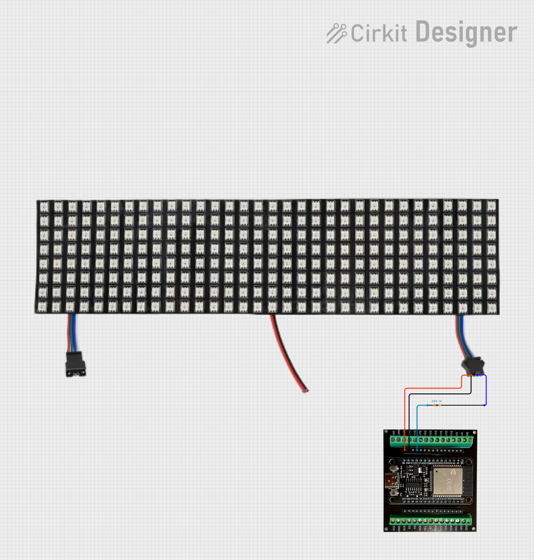
This document provides a detailed overview of a circuit that includes an ESP32 microcontroller, a WS2812 LED matrix, and a resistor. The ESP32 serves as the main controller, interfacing with the LED matrix through a resistor to ensure proper signal levels. The circuit is designed to control the LED matrix using the ESP32.
Component List
ESP32 (30 PIN) on Breakout Board
- Description: A versatile microcontroller with built-in Wi-Fi and Bluetooth capabilities.
- Pins: 3V3, GND, D15, D2, D4, D16, D17, D5, D18, D19, D21, RX0, TX0, D22, D23, EN, VP, VN, D34, D35, D32, D33, D25, D26, D27, D14, D12, D13, VIN, USB-C
- Purpose in Circuit: Main controller for the circuit, responsible for driving the LED matrix.
WS2812 LED Matrix 32x8
- Description: A matrix of individually addressable RGB LEDs.
- Pins: GND, VCC, DATAOUT, DATAIN
- Purpose in Circuit: Display component, controlled by the ESP32 to show various patterns and colors.
Resistor
- Description: A passive electrical component that provides resistance to the flow of current.
- Pins: pin1, pin2
- Properties:
- Resistance: 220 Ohms
- Purpose in Circuit: Used to limit the current and ensure proper signal levels between the ESP32 and the LED matrix.
Wiring Details
ESP32 (30 PIN) on Breakout Board
- D12 is connected to pin1 of the Resistor.
- GND is connected to GND of the WS2812 LED Matrix.
- VIN is connected to VCC of the WS2812 LED Matrix.
WS2812 LED Matrix 32x8
- GND is connected to GND of the ESP32.
- VCC is connected to VIN of the ESP32.
- DATAIN is connected to pin2 of the Resistor.
Resistor
- pin1 is connected to D12 of the ESP32.
- pin2 is connected to DATAIN of the WS2812 LED Matrix.
Code
There is no code provided for this circuit.
This document provides a comprehensive overview of the components and their interconnections in the circuit. The ESP32 microcontroller interfaces with the WS2812 LED matrix through a resistor to control the LED display.