
LDR-Controlled LED Dimmer with LM358 Op-Amp and NPN Transistor
View and Edit Project In Cirkit Designer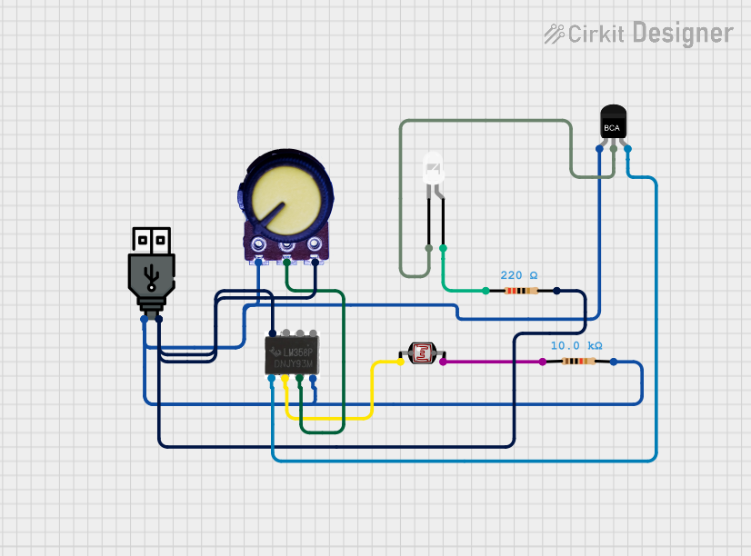
Circuit Documentation
Summary
This document provides a detailed overview of a light-sensitive circuit that utilizes a photocell (LDR) to detect ambient light levels and control the brightness of an LED through an LM358 operational amplifier (op-amp) and an NPN transistor. The circuit's sensitivity can be adjusted using a potentiometer. The circuit is powered by a USB power source.
Component List
Photocell (LDR)
- Description: A light-dependent resistor whose resistance varies with the ambient light level.
- Pins: pin 0, pin 1
Potentiometer
- Description: A variable resistor that can be adjusted to change the resistance.
- Pins: GND, Output, VCC
LM358 Op-Amp
- Description: A dual operational amplifier used for signal amplification and conditioning.
- Pins: 1, 2, 3, 4, 5, 6, 7, 8
NPN-Transistor
- Description: A bipolar junction transistor used as a switch or amplifier.
- Pins: E (Emitter), C (Collector), B (Base)
LED: Two Pin (white)
- Description: A white light-emitting diode used as an output indicator.
- Pins: cathode, anode
Resistor (10k Ohms)
- Description: A fixed resistor with a resistance of 10,000 Ohms.
- Pins: pin1, pin2
Resistor (220 Ohms)
- Description: A fixed resistor with a resistance of 220 Ohms.
- Pins: pin1, pin2
USB power
- Description: A power source that provides a regulated 5V supply from a USB port.
- Pins: + (VCC), - (GND)
Wiring Details
Photocell (LDR)
- pin 0 connected to LM358 Op-Amp pin 2
- pin 1 connected to Resistor (10k Ohms) pin1
Potentiometer
- GND connected to NPN-Transistor E, Resistor (10k Ohms) pin2, USB power -, LM358 Op-Amp pin 4
- Output connected to LM358 Op-Amp pin 3
- VCC connected to Resistor (220 Ohms) pin2, USB power +, LM358 Op-Amp pin 8
LM358 Op-Amp
- pin 1 connected to NPN-Transistor B
- pin 2 connected to Photocell (LDR) pin 0
- pin 3 connected to Potentiometer Output
- pin 4 connected to Potentiometer GND, NPN-Transistor E, Resistor (10k Ohms) pin2, USB power -
- pin 8 connected to Resistor (220 Ohms) pin2, Potentiometer VCC, USB power +
NPN-Transistor
- E (Emitter) connected to Potentiometer GND, Resistor (10k Ohms) pin2, USB power -, LM358 Op-Amp pin 4
- C (Collector) connected to LED: Two Pin (white) cathode
- B (Base) connected to LM358 Op-Amp pin 1
LED: Two Pin (white)
- cathode connected to NPN-Transistor C
- anode connected to Resistor (220 Ohms) pin1
Resistor (10k Ohms)
- pin1 connected to Photocell (LDR) pin 1
- pin2 connected to Potentiometer GND, NPN-Transistor E, USB power -, LM358 Op-Amp pin 4
Resistor (220 Ohms)
- pin1 connected to LED: Two Pin (white) anode
- pin2 connected to Potentiometer VCC, USB power +, LM358 Op-Amp pin 8
USB power
- + (VCC) connected to Resistor (220 Ohms) pin2, Potentiometer VCC, LM358 Op-Amp pin 8
- - (GND) connected to Potentiometer GND, NPN-Transistor E, Resistor (10k Ohms) pin2, LM358 Op-Amp pin 4
Documented Code
There is no embedded code provided for this circuit as it appears to be a purely analog design. If a microcontroller is added to the circuit in the future, the code will be documented in this section.