Cirkit Designer
Your all-in-one circuit design IDE
Home /
Project Documentation
Battery-Powered DC Motor Control with USB Charging and LED Indicator

Circuit Documentation
Summary of the Circuit
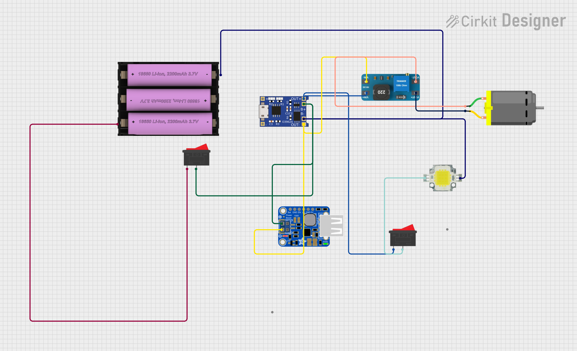
This circuit appears to be a power management and motor control system. It includes a DC motor, a charging module (TP4056), a power LED, a PowerBoost converter, a Li-ion battery, two rocker switches, and a boost converter (MT3608). The circuit is designed to drive a DC motor with power regulation and battery charging capabilities. The power LED indicates the status of the system, and the rocker switches provide manual control over the power flow.
Component List
DC Motor
- Description: A standard DC motor used for converting electrical energy into mechanical motion.
- Pins: pin 1, pin 2
TP4056
- Description: A lithium battery charging module with battery protection.
- Pins: OUT-, B-, B+, OUT+, IN-, IN+
Power LED 12V 10W 0.8-0.9A
- Description: A high-power LED used as an indicator light.
- Pins: +, -
PowerBoost 1000 Basic Terminal USB
- Description: A 5V boost converter with a USB output for powering USB devices.
- Pins: VBAT, GND, ENABLE, LBO, 5.0V
Li-ion battery, 2200 mAh 11.1 V
- Description: A rechargeable lithium-ion battery providing power to the circuit.
- Pins: +, -
Rocker Switch
- Description: A mechanical switch used to control the connection of a circuit.
- Pins: 1, 2
Boost Converter MT3608
- Description: A step-up voltage converter to increase voltage from a lower voltage battery.
- Pins: OUTPUT +, OUTPUT -, INPUT +, INPUT -
Wiring Details
DC Motor
- pin 1: Connected to the OUTPUT - of the boost converter MT3608.
- pin 2: Connected to the OUTPUT + of the boost converter MT3608.
TP4056
- OUT-: Connected to the INPUT - of the boost converter MT3608 and GND of the PowerBoost 1000 Basic Terminal USB.
- B-: Connected to the - pin of the Power LED 12V 10W 0.8-0.9A and the - pin of the Li-ion battery.
- B+: Connected to the pin 2 of the Rocker Switch and VBAT of the PowerBoost 1000 Basic Terminal USB.
- OUT+: Connected to the pin 1 of the Rocker Switch and INPUT + of the boost converter MT3608.
- IN-: Not connected in the provided net list.
- IN+: Not connected in the provided net list.
Power LED 12V 10W 0.8-0.9A
- +: Connected to the pin 2 of the Rocker Switch.
- -: Connected to the B- of the TP4056 and the - pin of the Li-ion battery.
PowerBoost 1000 Basic Terminal USB
- VBAT: Connected to the B+ of the TP4056.
- GND: Connected to the OUT- of the TP4056.
- ENABLE: Not connected in the provided net list.
- LBO: Not connected in the provided net list.
- 5.0V: Not connected in the provided net list.
Li-ion battery, 2200 mAh 11.1 V
- +: Connected to the pin 1 of the Rocker Switch.
- -: Connected to the B- of the TP4056 and the - pin of the Power LED 12V 10W 0.8-0.9A.
Rocker Switch (First Instance)
- 1: Connected to the B+ of the TP4056.
- 2: Connected to the + pin of the Li-ion battery.
Rocker Switch (Second Instance)
- 1: Connected to the OUT+ of the TP4056.
- 2: Connected to the + pin of the Power LED 12V 10W 0.8-0.9A.
Boost Converter MT3608
- OUTPUT +: Connected to the pin 2 of the DC Motor.
- OUTPUT -: Connected to the pin 1 of the DC Motor.
- INPUT +: Connected to the OUT+ of the TP4056.
- INPUT -: Connected to the OUT- of the TP4056.
Documented Code
No code has been provided for any microcontrollers in the circuit. If there are any programmable components or microcontrollers in the future, the code will be documented in this section.