Cirkit Designer
Your all-in-one circuit design IDE
Home /
Project Documentation
Arduino and ESP8266-Based Water Monitoring System with Flow Rate Sensor
Circuit Documentation
Summary
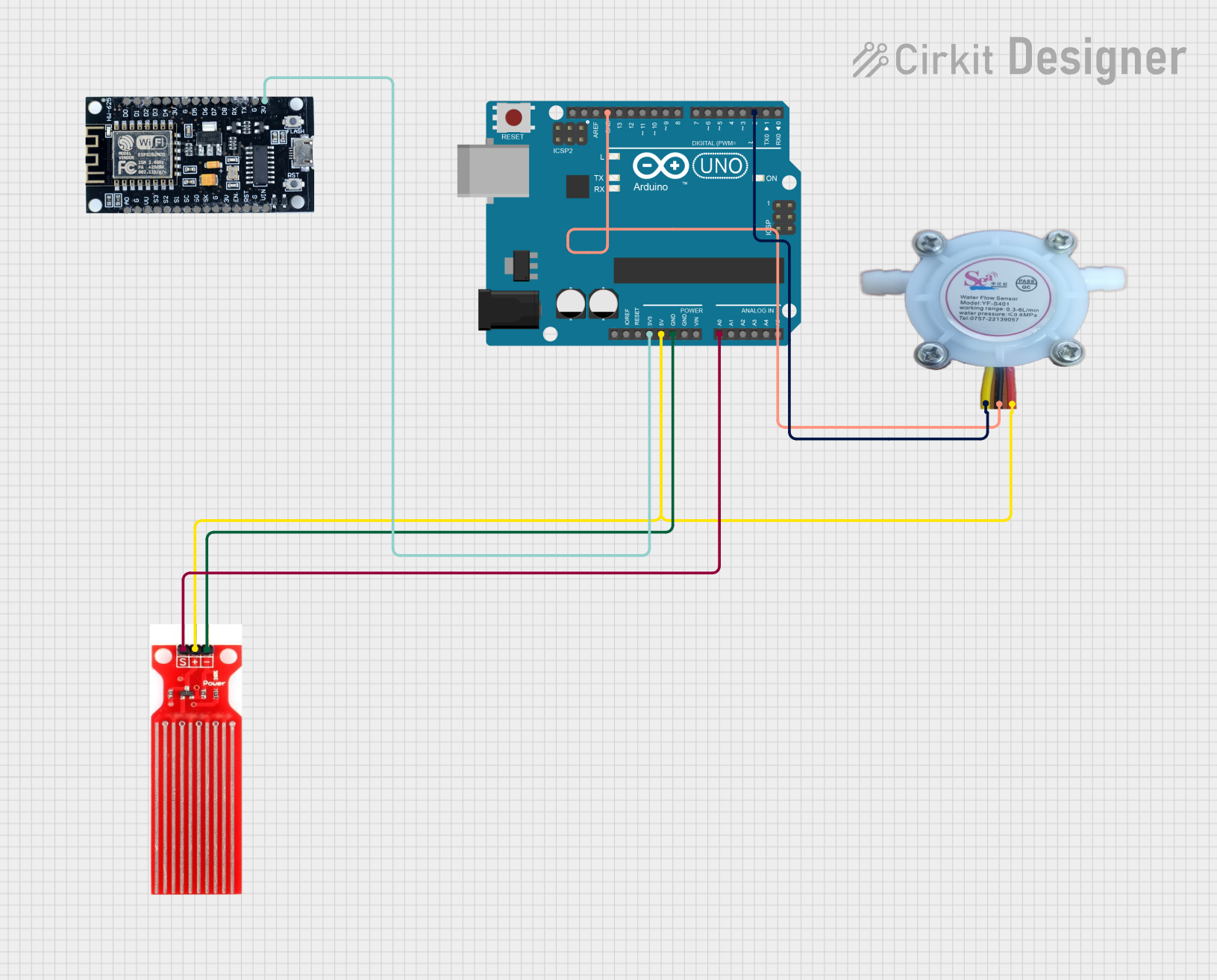
This circuit involves an Arduino UNO, an ESP8266 module, a water sensor, and a water flow rate sensor (YF-S401). The Arduino UNO serves as the main microcontroller, interfacing with the water sensor and the water flow rate sensor to read and process data. The ESP8266 module is powered by the Arduino UNO but is not directly interfaced in this circuit.
Component List
Arduino UNO
- Description: A microcontroller board based on the ATmega328P.
- Pins: UNUSED, IOREF, Reset, 3.3V, 5V, GND, Vin, A0, A1, A2, A3, A4, A5, SCL, SDA, AREF, D13, D12, D11, D10, D9, D8, D7, D6, D5, D4, D3, D2, D1, D0
ESP8266
- Description: A low-cost Wi-Fi microchip with full TCP/IP stack and microcontroller capability.
- Pins: 3V, G, D8, D7, D6, D5, D4, D3, D2, D1, D0, A0, S3, S2, S1, SC, S0, SK, EN, VIN, RST, VU
Water Sensor
- Description: A sensor used to detect the presence of water.
- Pins: Signal, VCC, GND
Water Flow Rate Sensor YF-S401
- Description: A sensor used to measure the flow rate of water.
- Pins: GND negative, IN positive, OUT signal output
Wiring Details
Arduino UNO
- A0: Connected to the Signal pin of the Water Sensor.
- 5V: Connected to the VCC pin of the Water Sensor and the IN positive pin of the Water Flow Rate Sensor YF-S401.
- GND: Connected to the GND pin of the Water Sensor and the GND negative pin of the Water Flow Rate Sensor YF-S401.
- 3.3V: Connected to the 3V pin of the ESP8266.
- D2: Connected to the OUT signal output pin of the Water Flow Rate Sensor YF-S401.
ESP8266
- 3V: Connected to the 3.3V pin of the Arduino UNO.
Water Sensor
- Signal: Connected to the A0 pin of the Arduino UNO.
- VCC: Connected to the 5V pin of the Arduino UNO.
- GND: Connected to the GND pin of the Arduino UNO.
Water Flow Rate Sensor YF-S401
- GND negative: Connected to the GND pin of the Arduino UNO.
- IN positive: Connected to the 5V pin of the Arduino UNO.
- OUT signal output: Connected to the D2 pin of the Arduino UNO.
Documented Code
Water Sensor Code (Arduino UNO)
const int waterSensorPin = A0; // Pin connected to the water sensor signal

void setup() {
  Serial.begin(9600); // Start serial communication for debugging
}

void loop() {
  int sensorValue = analogRead(waterSensorPin); // Read the analog value from the water sensor
  Serial.print("Water Sensor Value: ");
  Serial.println(sensorValue); // Print the sensor value to the Serial Monitor

  delay(1000); // Wait for 1 second before taking another reading
}
Water Flow Rate Sensor Code (Arduino UNO)
const int flowSensorPin = 2; // Pin connected to the flow sensor signal
volatile int pulseCount = 0;
unsigned long oldTime = 0;
float flowRate = 0.0;

void setup() {
  pinMode(flowSensorPin, INPUT_PULLUP); // Set the flow sensor pin as an input with an internal pull-up resistor
  attachInterrupt(digitalPinToInterrupt(flowSensorPin), pulseCounter, FALLING); // Attach an interrupt to the flow sensor pin
  Serial.begin(9600); // Start serial communication for debugging
}

void loop() {
  if ((millis() - oldTime) > 1000) { // Only process once per second
    detachInterrupt(digitalPinToInterrupt(flowSensorPin)); // Disable the interrupt while calculating

    // Calculate the flow rate in liters per minute
    flowRate = (pulseCount / 7.5); // YF-S401: 7.5 pulses per second per liter/minute

    Serial.print("Flow rate: ");
    Serial.print(flowRate);
    Serial.println(" L/min");

    pulseCount = 0; // Reset the pulse count
    oldTime = millis(); // Update the time

    attachInterrupt(digitalPinToInterrupt(flowSensorPin), pulseCounter, FALLING); // Re-enable the interrupt
  }
}

void pulseCounter() {
  pulseCount++; // Increment the pulse count
}