Cirkit Designer
Your all-in-one circuit design IDE
Home /
Project Documentation
Arduino Mega 2560 Controlled Bluetooth Relay for AC LED Bulbs
Circuit Documentation
Summary of the Circuit
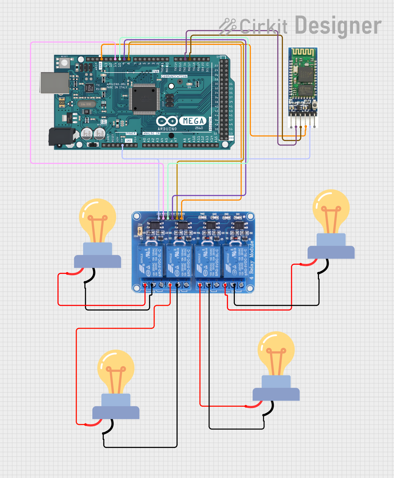
This circuit is designed to control multiple AC-powered LED bulbs using an Arduino Mega 2560 microcontroller and a 4-channel 5V relay module. The circuit also includes a Bluetooth module for potential wireless communication. The Arduino Mega 2560 is responsible for controlling the relay module, which in turn switches the LED bulbs on and off. The Bluetooth module is connected to the Arduino and can be used for remote control or data exchange.
Component List
Arduino Mega 2560
- Description: A microcontroller board based on the ATmega2560.
- Pins: IOREF, RESET, 3V3, 5V, GND, VIN, A0-A15, D0-D53, AREF, SDA, SCL.
Relay 4 Channel 5v
- Description: A 4-channel relay module that can control up to four high-power devices.
- Pins: GND, IN1-IN4, VCC, COM1-COM4, NO1-NO4, NC1-NC4.
Bluetooth Module
- Description: A wireless communication module that enables Bluetooth connectivity.
- Pins: EN, VCC, GND, TXD, RXD, STATE.
LED Bulb AC (4x)
- Description: An AC-powered LED bulb.
- Pins: +, -.
Wiring Details
Arduino Mega 2560
- GND connected to Relay Module GND and Bluetooth Module GND.
- Pin D8 PWM connected to Relay Module IN1.
- Pin D9 PWM connected to Relay Module IN2.
- Pin D10 PWM connected to Relay Module IN3.
- Pin D11 PWM connected to Relay Module IN4.
- 5V connected to Relay Module VCC and Bluetooth Module VCC.
- Pin D17 PWM/RX2 connected to Bluetooth Module TXD.
- Pin D16 PWM/TX2 connected to Bluetooth Module RXD.
Relay 4 Channel 5v
- GND connected to Arduino Mega 2560 GND.
- IN1-IN4 connected to Arduino Mega 2560 Pins D8-D11 respectively.
- VCC connected to Arduino Mega 2560 5V.
- COM1-COM4 connected to the negative (-) pins of each LED Bulb AC.
- NO1-NO4 connected to the positive (+) pins of each LED Bulb AC.
Bluetooth Module
- GND connected to Arduino Mega 2560 GND.
- VCC connected to Arduino Mega 2560 5V.
- TXD connected to Arduino Mega 2560 Pin D17 PWM/RX2.
- RXD connected to Arduino Mega 2560 Pin D16 PWM/TX2.
LED Bulb AC
- The negative (-) pin of each LED Bulb AC connected to the corresponding COM pin on the Relay Module.
- The positive (+) pin of each LED Bulb AC connected to the corresponding NO pin on the Relay Module.
Documented Code
Arduino Mega 2560 Code (sketch.ino)
void setup() {
  // put your setup code here, to run once:

}

void loop() {
  // put your main code here, to run repeatedly:

}
Additional Notes
- The provided code is a template and does not contain any functional code to control the relay module or communicate with the Bluetooth module. The user must implement the control logic in the
setup()andloop()functions. - The Bluetooth module's EN and STATE pins are not connected in the current wiring configuration. If these features are required, additional connections and code will be necessary.