
ESP32-Based Smart Timer with Keypad and LCD Display for Water Pump Control
View and Edit Project In Cirkit Designer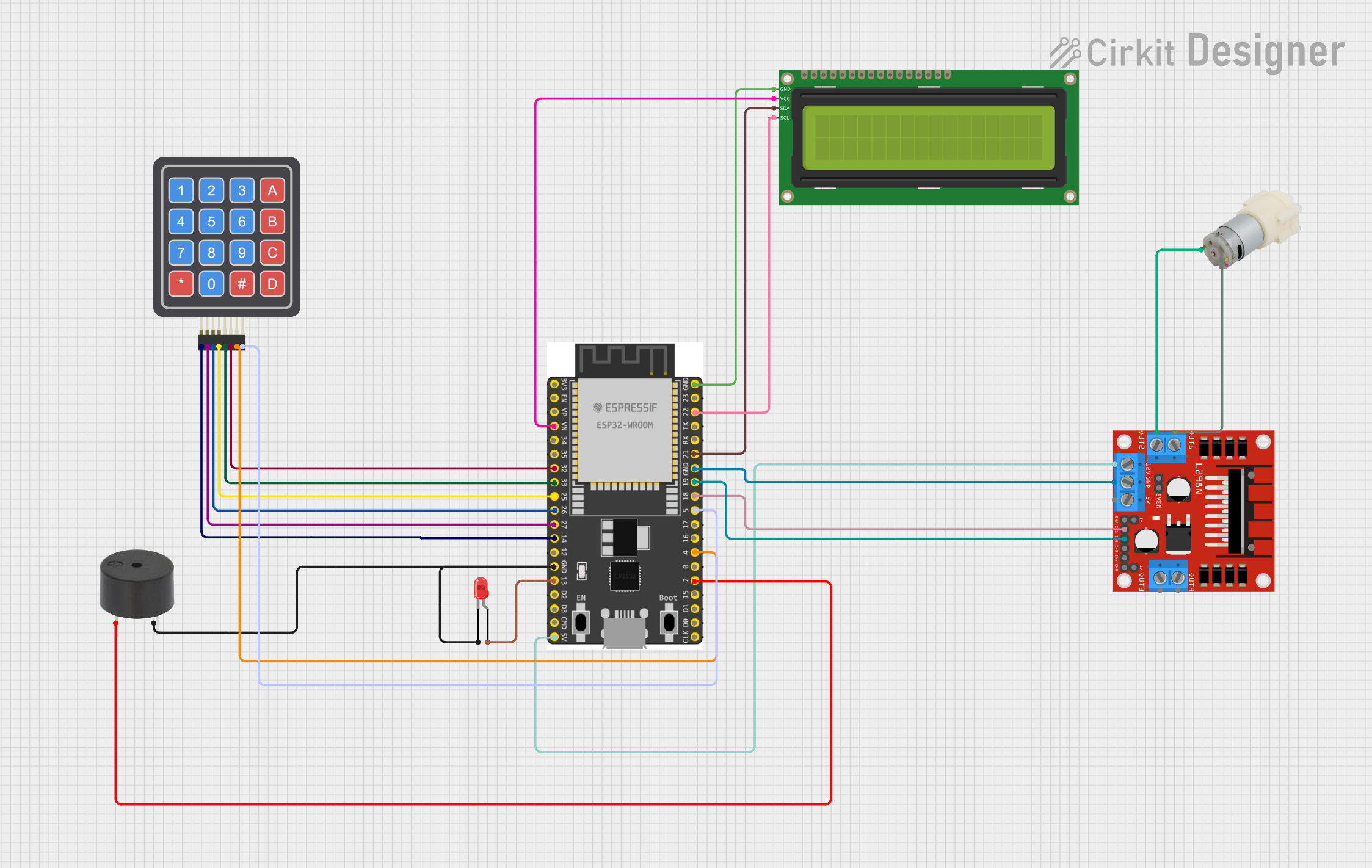
Circuit Documentation
Summary
This circuit is designed to control a water pump using an ESP32 microcontroller. The system includes a 4x4 keypad for user input, a 16x2 I2C LCD for display, an L298N motor driver to control the water pump, a buzzer for audio alerts, and an LED for visual indicators. The user can set a timer using the keypad, and the water pump will run for the specified duration. The LCD displays the remaining time, and the buzzer sounds when the timer ends.
Component List
ESP32 Wroom Dev Kit
- Description: A powerful microcontroller with Wi-Fi and Bluetooth capabilities.
- Pins: 3V3, EN, VP, VN, GPIO 34, GPIO 35, GPIO 32, GPIO 33, GPIO 25, GPIO 26, GPIO 27, GPIO 14, GND, GPIO 13, SD2, SD3, CMD, V5, GPIO 23, GPIO 22, TXD, RXD, GPIO 21, GPIO 19, GPIO 18, GPIO 5, GPIO 17, GPIO 16, GPIO 4, GPIO 0, GPIO 2, GPIO 15, SD1, SD0, CLK
Water Pump 12V
- Description: A 12V DC water pump.
- Pins: +, -
4x4 Keypad (Simulator)
- Description: A 4x4 matrix keypad for user input.
- Pins: R1, C4, R2, C2, R3, R4, C1, C3
L298N DC Motor Driver
- Description: A dual H-Bridge motor driver for controlling DC motors.
- Pins: OUT1, OUT2, 12V, GND, 5V, OUT3, OUT4, 5V-ENA-JMP-I, 5V-ENA-JMP-O, +5V-J1, +5V-J2, ENA, IN1, IN2, IN3, IN4, ENB
16x2 I2C LCD
- Description: A 16x2 character LCD with I2C interface.
- Pins: GND, VCC, SDA, SCL
Buzzer
- Description: A simple buzzer for audio alerts.
- Pins: PIN, GND
LED: Two Pin (Red)
- Description: A red LED for visual indicators.
- Pins: Cathode, Anode
Wiring Details
ESP32 Wroom Dev Kit
- VN to VCC of 16x2 I2C LCD
- GPIO 32 to C2 of 4x4 Keypad
- GPIO 33 to C1 of 4x4 Keypad
- GPIO 25 to R4 of 4x4 Keypad
- GPIO 26 to R3 of 4x4 Keypad
- GPIO 27 to R2 of 4x4 Keypad
- GPIO 14 to R1 of 4x4 Keypad
- GND to GND of 16x2 I2C LCD
- GND to GND of Buzzer
- GND to GND of L298N DC Motor Driver
- GPIO 13 to Anode of LED
- V5 to 12V of L298N DC Motor Driver
- GPIO 22 to SCL of 16x2 I2C LCD
- GPIO 21 to SDA of 16x2 I2C LCD
- GPIO 19 to IN2 of L298N DC Motor Driver
- GPIO 18 to IN1 of L298N DC Motor Driver
- GPIO 5 to C4 of 4x4 Keypad
- GPIO 4 to C3 of 4x4 Keypad
- GPIO 2 to PIN of Buzzer
Water Pump 12V
- + to OUT1 of L298N DC Motor Driver
- - to OUT2 of L298N DC Motor Driver
4x4 Keypad (Simulator)
- C2 to GPIO 32 of ESP32 Wroom Dev Kit
- C1 to GPIO 33 of ESP32 Wroom Dev Kit
- R4 to GPIO 25 of ESP32 Wroom Dev Kit
- R3 to GPIO 26 of ESP32 Wroom Dev Kit
- R2 to GPIO 27 of ESP32 Wroom Dev Kit
- R1 to GPIO 14 of ESP32 Wroom Dev Kit
- C4 to GPIO 5 of ESP32 Wroom Dev Kit
- C3 to GPIO 4 of ESP32 Wroom Dev Kit
L298N DC Motor Driver
- 12V to V5 of ESP32 Wroom Dev Kit
- GND to GND of ESP32 Wroom Dev Kit
- IN2 to GPIO 19 of ESP32 Wroom Dev Kit
- IN1 to GPIO 18 of ESP32 Wroom Dev Kit
- OUT1 to + of Water Pump 12V
- OUT2 to - of Water Pump 12V
16x2 I2C LCD
- VCC to VN of ESP32 Wroom Dev Kit
- GND to GND of ESP32 Wroom Dev Kit
- SCL to GPIO 22 of ESP32 Wroom Dev Kit
- SDA to GPIO 21 of ESP32 Wroom Dev Kit
Buzzer
- PIN to GPIO 2 of ESP32 Wroom Dev Kit
- GND to GND of ESP32 Wroom Dev Kit
LED: Two Pin (Red)
- Anode to GPIO 13 of ESP32 Wroom Dev Kit
- Cathode to GND of ESP32 Wroom Dev Kit
Code Documentation
#include <Keypad.h>
#include <Ticker.h>
#include <Wire.h>
#include <LiquidCrystal_I2C.h>

const byte ROW_NUM = 4;
const byte COLUMN_NUM = 4;

char keys[ROW_NUM][COLUMN_NUM] = {
  {'1','2','3','A'},
  {'4','5','6','B'},
  {'7','8','9','C'},
  {'*','0','#','D'}
};

byte pin_rows[ROW_NUM] = {14, 27, 26, 25};
byte pin_column[COLUMN_NUM] = {33, 32, 35, 34};

Keypad keypad = Keypad(makeKeymap(keys), pin_rows, pin_column, ROW_NUM, COLUMN_NUM);

int timerSeconds = 0;
int initialTime = 0;

Ticker timerTicker;
Ticker ledTicker;

bool timerActive = false;
bool ledState = false;

LiquidCrystal_I2C lcd(0x27, 16, 2);

const int ledPin = 13;
const int buzzerPin = 12;

// Motor control pins for L298N motor driver
const int motorPin1 = 18; // IN1
const int motorPin2 = 19; // IN2

void setup() {
  Serial.begin(115200);

  lcd.begin();
  lcd.setBacklight(true);

  pinMode(ledPin, OUTPUT);
  pinMode(buzzerPin, OUTPUT);
  pinMode(motorPin1, OUTPUT);
  pinMode(motorPin2, OUTPUT);

  digitalWrite(buzzerPin, LOW);
  stopMotor();

  timerTicker.attach(1, timerTick);

  lcd.clear();
  lcd.setCursor(0, 0);
  lcd.print("Enter time in sec:");
  lcd.setCursor(0, 1);
  lcd.print("Use keys 0-9");
}

void loop() {
  char key = keypad.getKey();
  if (key) handleKeyInput(key);

  if (timerActive) updateDisplay();
}

void handleKeyInput(char key) {
  Serial.print("Key pressed: ");
  Serial.println(key);

  if (key >= '0' && key <= '9') {
    timerSeconds = timerSeconds * 10 + (key - '0');
    displayTimeSetting();
  }

  if (key == 'A' && timerSeconds > 0) startTimer();
  if (key == 'B') resetTimer();
}

void displayTimeSetting() {
  lcd.clear();
  lcd.setCursor(0, 0);
  lcd.print("Time set:");
  lcd.setCursor(0, 1);
  displayTime(timerSeconds);
}

void startTimer() {
  initialTime = timerSeconds;
  timerActive = true;
  lcd.clear();
  lcd