Cirkit Designer
Your all-in-one circuit design IDE
Home /
Project Documentation
Arduino UNO LED Blinker with Resistor
Circuit Documentation
Summary
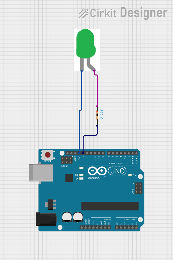
This circuit consists of an Arduino UNO microcontroller, a green LED, and a 200 Ohm resistor. The Arduino UNO is programmed to blink the LED on and off at one-second intervals.
Component List
Arduino UNO
- Description: A microcontroller board based on the ATmega328P.
- Pins: UNUSED, IOREF, Reset, 3.3V, 5V, GND, Vin, A0, A1, A2, A3, A4, A5, SCL, SDA, AREF, D13, D12, D11, D10, D9, D8, D7, D6, D5, D4, D3, D2, D1, D0
LED: Two Pin (green)
- Description: A green light-emitting diode.
- Pins: cathode, anode
Resistor
- Description: A resistor with a resistance of 200 Ohms.
- Pins: pin1, pin2
- Properties:
- Resistance: 200 Ohms
Wiring Details
Arduino UNO
- GND: Connected to the cathode of the LED.
- D13: Connected to pin2 of the resistor.
LED: Two Pin (green)
- cathode: Connected to GND of the Arduino UNO.
- anode: Connected to pin1 of the resistor.
Resistor
- pin1: Connected to the anode of the LED.
- pin2: Connected to D13 of the Arduino UNO.
Code Documentation
Arduino UNO Code
void setup() {
  pinMode(13, OUTPUT); // Set digital pin 13 (D13) as an output
}

void loop() {
  digitalWrite(13, HIGH); // Turn the LED on (HIGH is the voltage level)
  delay(1000);            // Wait for a second (1000 milliseconds)
  digitalWrite(13, LOW);  // Turn the LED off by making the voltage LOW
  delay(1000);            // Wait for a second
}
This code sets up digital pin 13 (D13) as an output. In the main loop, it turns the LED on by setting D13 to HIGH, waits for one second, then turns the LED off by setting D13 to LOW, and waits for another second. This cycle repeats indefinitely, causing the LED to blink on and off at one-second intervals.