
Arduino Mega 2560 Controlled Environmental System for Aquatic and Hydroponic Management
View and Edit Project In Cirkit Designer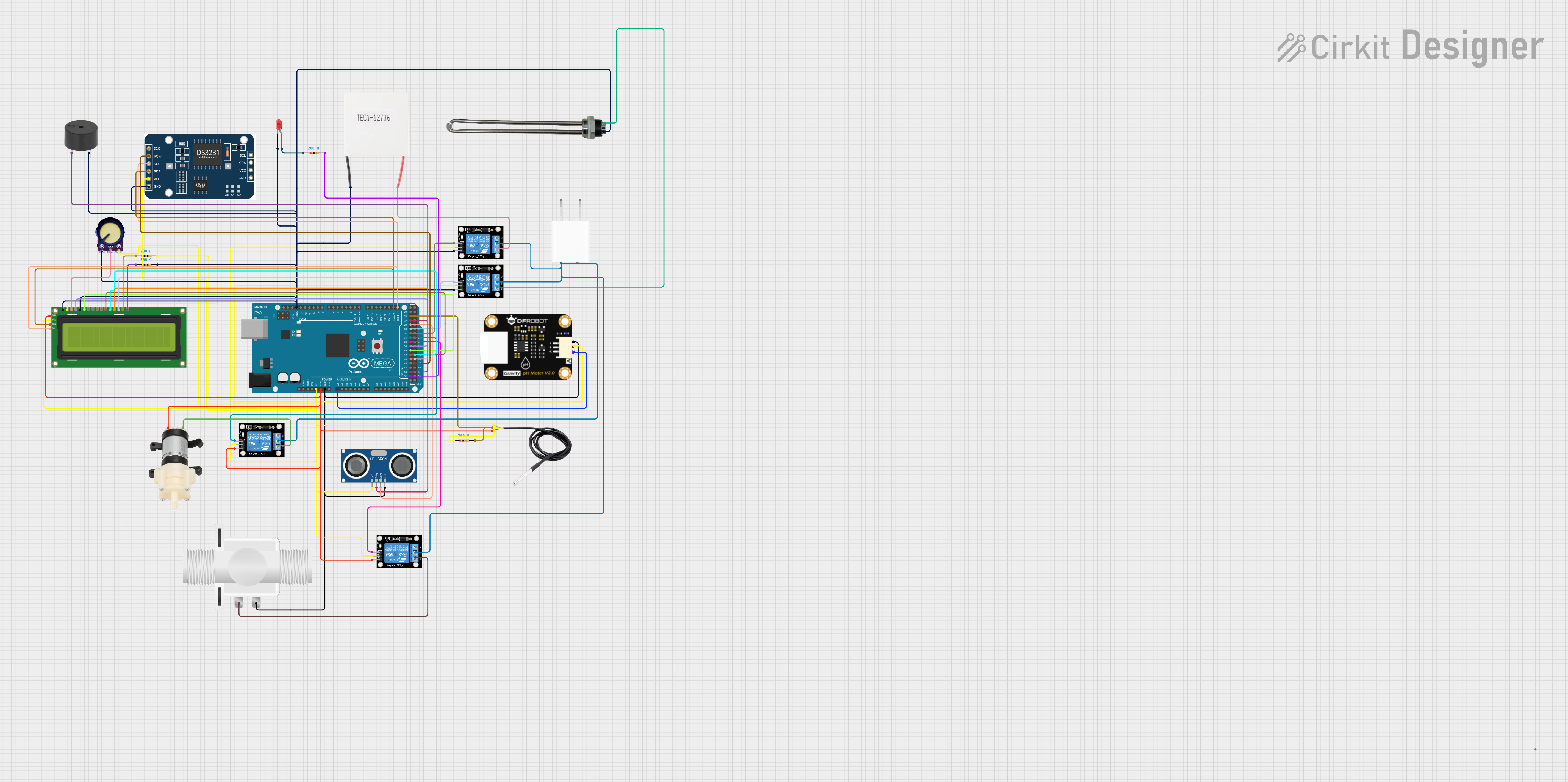
Circuit Documentation
Summary
This document provides a detailed overview of a circuit designed to interface various sensors, actuators, and modules with an Arduino Mega 2560 microcontroller. The circuit includes a pH sensor module, temperature sensor (DS18B20), ultrasonic sensor (HC-SR04), relay modules, a 5V adapter, a water heater, a Peltier module, a mini diaphragm water pump, a plastic solenoid valve, an I2C LCD 16x2 screen, potentiometers, resistors, an RTC module, a buzzer, and an LED. The circuit is powered by a 5V supply and includes I2C communication, digital I/O, and analog input functionalities.
Component List
- Arduino Mega 2560: A microcontroller board based on the ATmega2560, with numerous digital and analog I/O pins.
- pH Degree Sensor Module: A sensor module used to measure the pH level of a solution.
- DS18B20: A digital temperature sensor that provides temperature readings over a 1-Wire interface.
- Resistor: A passive component used to limit current or divide voltages in the circuit. Multiple resistors with a resistance of 200 Ohms are used.
- HC-SR04 Ultrasonic Sensor: A sensor used to measure distance through ultrasonic waves.
- Relay module 1 channel: An electrically operated switch that allows controlling high power devices with low power signals. Multiple single-channel relay modules are used.
- 5V Adapter: A power supply module that converts AC input to a 5V DC output.
- Water Heater: A device used to heat water.
- Peltier Module: A thermoelectric device used for heating or cooling.
- Mini Diaphragm Water Pump: A pump used for moving water.
- Plastic Solenoid Valve: An electrically controlled valve used for controlling the flow of liquids.
- I2C LCD 16x2 Screen: A liquid crystal display that can show 16 characters per line, with 2 lines, using the I2C communication protocol.
- Potentiometer: A variable resistor used to adjust levels such as voltage.
- RTC Module: A real-time clock module to keep track of the current time.
- Buzzer: An audio signaling device.
- LED (red): A light-emitting diode that emits red light.
Wiring Details
Arduino Mega 2560
- 5V: Connected to various components for power supply.
- GND: Common ground for multiple components.
- A0: Connected to the pH sensor module for analog input.
- D21/SCL, D20/SDA: I2C communication pins connected to the I2C LCD screen and RTC module.
- D52, D50, D47, D45, D43, D44, D42, D40, D38, D36, D34, D32, D30, D28, D26, D24: Digital pins connected to various components for control and data acquisition.
pH Degree Sensor Module
- pH Negative: Connected to Arduino GND.
- pH Positive: Connected to 5V supply.
- pH A: Connected to Arduino A0 for analog input.
DS18B20
- Signal: Connected to Arduino D24 through a 200 Ohm resistor.
- GND: Connected to Arduino GND.
- VCC: Connected to 5V supply.
HC-SR04 Ultrasonic Sensor
- VCC: Connected to 5V supply.
- TRIG: Connected to Arduino D26 for trigger signal.
- ECHO: Connected to Arduino D28 for echo signal.
- GND: Connected to Arduino GND.
Relay Modules
- S: Control pins connected to various Arduino digital pins (D36, D34, D32, D30) for switching.
- 5V: Connected to 5V supply.
- GND: Connected to Arduino GND.
- NC: Normally closed contacts, not detailed in the wiring.
- COM: Common contacts connected to the 5V supply.
- NO: Normally open contacts connected to the Water Heater, Peltier Module, Mini Diaphragm Water Pump, and Plastic Solenoid Valve.
5V Adapter
- AC In 1, AC In 2: AC input terminals.
- 5V: Output connected to the common contacts (COM) of the relay modules.
- GND: Not detailed in the wiring.
Water Heater
- V+: Connected to the normally open (NO) contact of a relay module.
- V-: Connected to the common ground.
Peltier Module
- Positive: Connected to the normally open (NO) contact of a relay module.
- Negative: Connected to the common ground.
Mini Diaphragm Water Pump
- Positive (+): Connected to the normally open (NO) contact of a relay module.
- Negative (-): Connected to Arduino GND.
Plastic Solenoid Valve
- Pin1: Connected to the normally open (NO) contact of a relay module.
- Pin2: Connected to Arduino GND.
I2C LCD 16x2 Screen
- SCL, SDA: Connected to Arduino SCL (D21) and SDA (D20) for I2C communication.
- VCC (5V), VDD: Connected to 5V supply.
- GND, RW: Connected to the common ground.
- RS, E, D4, D5, D6, D7: Connected to Arduino digital pins (D38, D40, D42, D43, D45, D47) for control and data.
- VO: Connected to the output of a potentiometer for contrast adjustment.
- BLA: Connected to 5V through a 200 Ohm resistor.
- BLK: Connected to the common ground through a 200 Ohm resistor.
Potentiometer
- VCC: Connected to 5V supply.
- Output: Connected to the VO pin of the I2C LCD screen for contrast control.
- GND: Connected to the common ground.
RTC Module
- SCL, SDA: Connected to Arduino SCL (D21) and SDA (D20) for I2C communication.
- VCC: Connected to 5V supply.
- GND: Connected to the common ground.
- SQW: Connected to Arduino D47 for square wave output.
Buzzer
- PIN: Connected to Arduino D50 for control.
- GND: Connected to the common ground.
LED (red)
- Anode: Connected to Arduino D52 through a 200 Ohm resistor.
- Cathode: Connected to the common ground.
Documented Code
Arduino Mega 2560 Code (sketch.ino)
void setup() {
  // put your setup code here, to run once:

}

void loop() {
  // put your main code here, to run repeatedly:

}
This code template provides the basic structure for an Arduino sketch with empty setup and loop functions. The setup function is intended for initialization code that runs once, while the loop function contains code that runs repeatedly, forming the main logic of the microcontroller program.