
Arduino Uno Clap-Activated Smart Light with KY-038 Sound Sensor and Relay
View and Edit Project In Cirkit Designer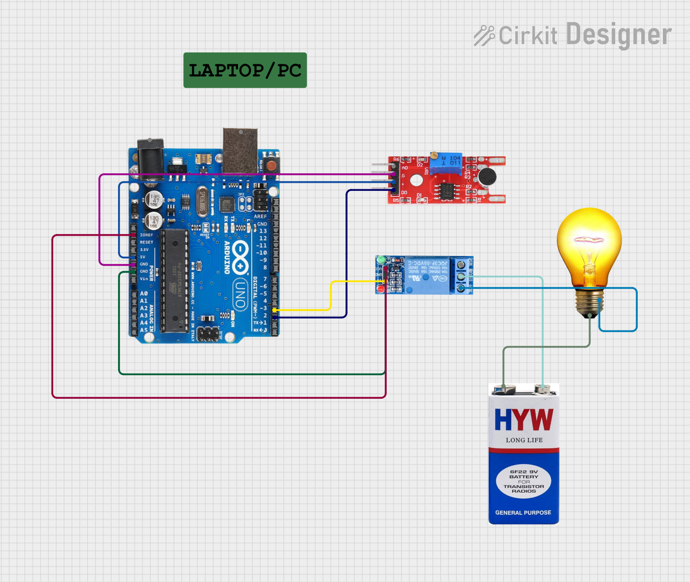
Circuit Documentation
Summary
This circuit is a clap-activated switch that uses a sound sensor to detect claps and control an AC bulb through a relay module. The core of the circuit is an Arduino Uno R3 microcontroller, which processes the input from the sound sensor and toggles the relay to turn the AC bulb on or off.
Component List
KY 038 Sound Sensor
- Pins: +, G, A0, D0
- Description: Detects sound and outputs a digital signal when a sound is detected.
- Purpose in Circuit: To detect claps and send a signal to the Arduino.
9V Battery
- Pins: +, -
- Description: Provides power to the AC bulb.
- Purpose in Circuit: To power the AC bulb through the relay.
Arduino Uno R3
- Pins: D8, D9, D10, D11, D12, D13, GND, AREF, SDA, SCL, D0/RX, D1/Tx, D2, D3, D4, D5, 6, D7, A5/SCL, A4/SDA, A3, A2, A1, A0, Vin, 5V, 3.3V, RESET, IOREF, NONE, USB Jack, Power Jack
- Description: A microcontroller board based on the ATmega328P.
- Purpose in Circuit: To process the input from the sound sensor and control the relay.
AC Bulb
- Pins: P, N
- Description: Standard AC bulb.
- Purpose in Circuit: To be turned on or off based on the relay state.
1 Channel Relay 5V
- Pins: VCC, GND, IN, NC, COM, NO
- Description: A relay module that can be controlled by a 5V signal.
- Purpose in Circuit: To switch the AC bulb on or off based on the signal from the Arduino.
Wiring Details
KY 038 Sound Sensor
- +: Connected to 5V on Arduino Uno R3
- G: Connected to GND on Arduino Uno R3
- D0: Connected to D2 on Arduino Uno R3
9V Battery
- +: Connected to P on AC Bulb
- -: Connected to COM on 1 Channel Relay 5V
Arduino Uno R3
- D2: Connected to D0 on KY 038 Sound Sensor
- D3: Connected to IN on 1 Channel Relay 5V
- GND: Connected to GND on KY 038 Sound Sensor
- GND: Connected to GND on 1 Channel Relay 5V
- 5V: Connected to + on KY 038 Sound Sensor
- IOREF: Connected to VCC on 1 Channel Relay 5V
AC Bulb
- P: Connected to + on 9V Battery
- N: Connected to NC on 1 Channel Relay 5V
1 Channel Relay 5V
- VCC: Connected to IOREF on Arduino Uno R3
- GND: Connected to GND on Arduino Uno R3
- IN: Connected to D3 on Arduino Uno R3
- NC: Connected to N on AC Bulb
- COM: Connected to - on 9V Battery
Code Documentation
// Pin definitions
const int soundSensorPin = 2; // Pin connected to the sound sensor output
const int relayPin = 3;       // Pin connected to the relay module

bool relayState = false;      // Tracks the relay state (ON/OFF)
unsigned long lastClapTime = 0;
const unsigned long debounceDelay = 300; // Debounce delay in milliseconds

void setup() {
  pinMode(soundSensorPin, INPUT);
  pinMode(relayPin, OUTPUT);

  digitalWrite(relayPin, LOW); // Initialize relay to OFF
  Serial.begin(9600);
  Serial.println("Clap Switch is ready!");
}

void loop() {
  // Read the sound sensor state
  int sensorValue = digitalRead(soundSensorPin);

  // If a clap (sound detected) is registered
  if (sensorValue == HIGH) {
    unsigned long currentTime = millis();

    // Check debounce delay to avoid false triggering
    if (currentTime - lastClapTime > debounceDelay) {
      relayState = !relayState;             // Toggle relay state
      digitalWrite(relayPin, relayState);   // Update relay state
      Serial.print("Relay State: ");
      Serial.println(relayState ? "ON" : "OFF");

      lastClapTime = currentTime;           // Update last clap time
    }
  }
}
This code initializes the sound sensor and relay pin, and continuously checks for a clap sound. When a clap is detected, it toggles the relay state, turning the AC bulb on or off. The debounce delay ensures that the relay is not triggered multiple times for a single clap.