
Arduino UNO-Based Obstacle Avoidance and Boundary Detection Robot with IR Sensors and L298N Motor Driver
View and Edit Project In Cirkit Designer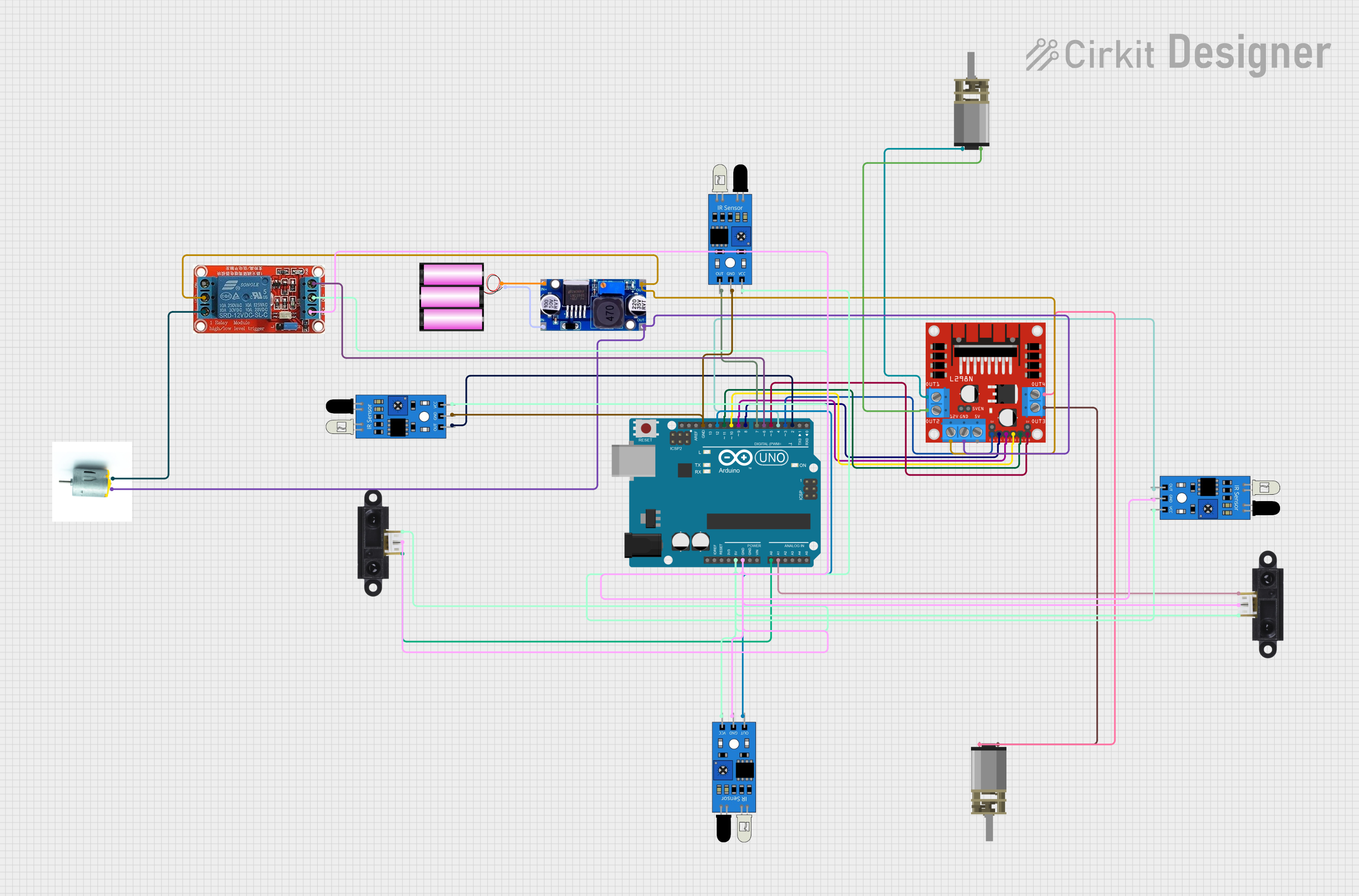
Circuit Documentation
Summary
This document provides a detailed overview of a circuit designed to control a robotic vehicle using an Arduino UNO microcontroller. The circuit includes various sensors for obstacle and boundary detection, motor drivers for controlling the vehicle's movement, and a relay for additional control. The Arduino UNO is programmed to read sensor inputs and control the motors accordingly.
Component List
Arduino UNO
- Description: Microcontroller board based on the ATmega328P.
- Pins: UNUSED, IOREF, Reset, 3.3V, 5V, GND, Vin, A0, A1, A2, A3, A4, A5, SCL, SDA, AREF, D13, D12, D11, D10, D9, D8, D7, D6, D5, D4, D3, D2, D1, D0
L298N DC Motor Driver
- Description: Dual H-Bridge motor driver.
- Pins: OUT1, OUT2, 12V, GND, 5V, OUT3, OUT4, 5V-ENA-JMP-I, 5V-ENA-JMP-O, +5V-J1, +5V-J2, ENA, IN1, IN2, IN3, IN4, ENB
IR Sensor
- Description: Infrared sensor for obstacle detection.
- Pins: out, gnd, vcc
Sharp IR Sensor
- Description: Infrared distance sensor.
- Pins: VCC, GND, Pin
LM2596
- Description: DC-DC buck converter.
- Pins: IN, OUT
DC Mini Metal Gear Motor
- Description: Small DC motor with metal gears.
- Pins: IN1, IN2
Motor
- Description: Generic motor.
- Pins: negative, positive
Battery 12V
- Description: 12V battery for power supply.
- Pins: +, -
12V Relay
- Description: Relay module for switching.
- Pins: NO, COM, NC, IN, DC-, DC+
Wiring Details
Arduino UNO
- 5V: Connected to vcc of IR sensors and Sharp IR sensors.
- GND: Connected to gnd of IR sensors and Sharp IR sensors.
- A0: Connected to Pin of Sharp IR Sensor.
- A1: Connected to Pin of another Sharp IR Sensor.
- D12: Connected to out of an IR sensor.
- D11: Connected to IN4 of L298N DC motor driver.
- D10: Connected to IN3 of L298N DC motor driver.
- D9: Connected to IN2 of L298N DC motor driver.
- D8: Connected to IN1 of L298N DC motor driver.
- D7: Connected to out of an IR sensor.
- D6: Connected to IN of 12V Relay.
- D5: Connected to ENB of L298N DC motor driver.
- D4: Connected to out of an IR sensor.
- D3: Connected to ENA of L298N DC motor driver.
- D2: Connected to out of an IR sensor.
L298N DC Motor Driver
- IN4: Connected to D11 of Arduino UNO.
- IN3: Connected to D10 of Arduino UNO.
- IN2: Connected to D9 of Arduino UNO.
- IN1: Connected to D8 of Arduino UNO.
- ENB: Connected to D5 of Arduino UNO.
- ENA: Connected to D3 of Arduino UNO.
- OUT1: Connected to IN1 of a DC Mini Metal Gear Motor.
- OUT2: Connected to IN2 of the same DC Mini Metal Gear Motor.
- OUT3: Connected to IN1 of another DC Mini Metal Gear Motor.
- OUT4: Connected to IN2 of the same DC Mini Metal Gear Motor.
- 12V: Connected to OUT of LM2596 and COM of 12V Relay.
- GND: Connected to OUT of LM2596 and negative of Motor.
IR Sensor
- vcc: Connected to 5V of Arduino UNO.
- gnd: Connected to GND of Arduino UNO.
- out: Connected to D12, D7, D4, and D2 of Arduino UNO.
Sharp IR Sensor
- VCC: Connected to 5V of Arduino UNO.
- GND: Connected to GND of Arduino UNO.
- Pin: Connected to A0 and A1 of Arduino UNO.
LM2596
- IN: Connected to + and - of Battery 12V.
- OUT: Connected to 12V and GND of L298N DC motor driver and COM of 12V Relay.
DC Mini Metal Gear Motor
- IN1: Connected to OUT1 and OUT3 of L298N DC motor driver.
- IN2: Connected to OUT2 and OUT4 of L298N DC motor driver.
Motor
- negative: Connected to GND of L298N DC motor driver.
- positive: Connected to NC of 12V Relay.
Battery 12V
- +: Connected to IN of LM2596.
- -: Connected to IN of LM2596.
12V Relay
- NO: Not connected.
- COM: Connected to 12V of L298N DC motor driver.
- NC: Connected to positive of Motor.
- IN: Connected to D6 of Arduino UNO.
- DC-: Connected to 5V of Arduino UNO.
- DC+: Connected to GND of Arduino UNO.
Documented Code
#include <Servo.h>

// Motor and ESC Pins
#define IN1 8   // Left motor forward
#define IN2 9   // Left motor backward
#define ENA 3   // Left motor speed control
#define IN3 10  // Right motor forward
#define IN4 11  // Right motor backward
#define ENB 5   // Right motor speed control
#define ESC_PIN 6

// Sensors
#define IR1_PIN 2    // IR sensor for boundary detection
#define IR2_PIN 4
#define IR3_PIN 7
#define IR4_PIN 12
#define DIST1_PIN A0 // Distance sensor 1
#define DIST2_PIN A1 // Distance sensor 2

Servo esc; // Servo object for ESC control

void setup() {
  // Motor Pins
  pinMode(IN1, OUTPUT);
  pinMode(IN2, OUTPUT);
  pinMode(ENA, OUTPUT);
  pinMode(IN3, OUTPUT);
  pinMode(IN4, OUTPUT);
  pinMode(ENB, OUTPUT);

  // Sensors
  pinMode(IR1_PIN, INPUT);
  pinMode(IR2_PIN, INPUT);
  pinMode(IR3_PIN, INPUT);
  pinMode(IR4_PIN, INPUT);

  // ESC setup
  esc.attach(ESC_PIN);
  esc.write(0); // Initialize ESC

  Serial.begin(9600);
}

void loop() {
  // Read sensors
  int dist1 = analogRead(DIST1_PIN); // Distance sensor 1
  int dist2 = analogRead(DIST2_PIN); // Distance sensor 2
  int ir1 = digitalRead(IR1_PIN);    // IR edge detection
  int ir2 = digitalRead(IR2_PIN);
  int ir3 = digitalRead(IR3_PIN);
  int ir4 = digitalRead(IR4_PIN);

  // Obstacle detection
  if (dist1 < 300 || dist2 < 300) { // Example threshold for obstacle
    stopMotors();
    Serial.println("Obstacle Detected!");
    if (dist1 < dist2) {
      turnRight(); // Turn away from closer obstacle
    } else {
      turnLeft();
    }
  }

  // Boundary detection
  if (ir1 == LOW || ir2 == LOW || ir3 == LOW || ir4 == LOW) {
    stopMotors();
    Serial.println("Boundary Detected!");
    reverse(); // Move backward slightly to avoid falling
    delay(500);
    turnRight(); // Turn to change direction
    delay(500);
  }

  // Default behavior
  moveForward();
}

// Movement functions
void moveForward() {
  // Both motors move forward
  digitalWrite(IN1, HIGH);
  digitalWrite(IN2, LOW);
  analogWrite(ENA, 150); // Left motor speed
  digitalWrite(IN3, HIGH);
  digitalWrite(IN4, LOW);
  analogWrite(ENB, 150); // Right motor speed
}

void stopMotors() {
  // Stop both motors
  digitalWrite(IN1, LOW);
  digitalWrite(IN2, LOW);
  digitalWrite(IN3, LOW);
  digitalWrite(IN4, LOW);
}

void reverse() {
  // Both motors move backward
  digitalWrite(IN1, LOW);
  digitalWrite(IN2, HIGH);
  analogWrite(ENA, 150); // Left motor speed
  digitalWrite