
Circuit Documentation
Summary of the Circuit
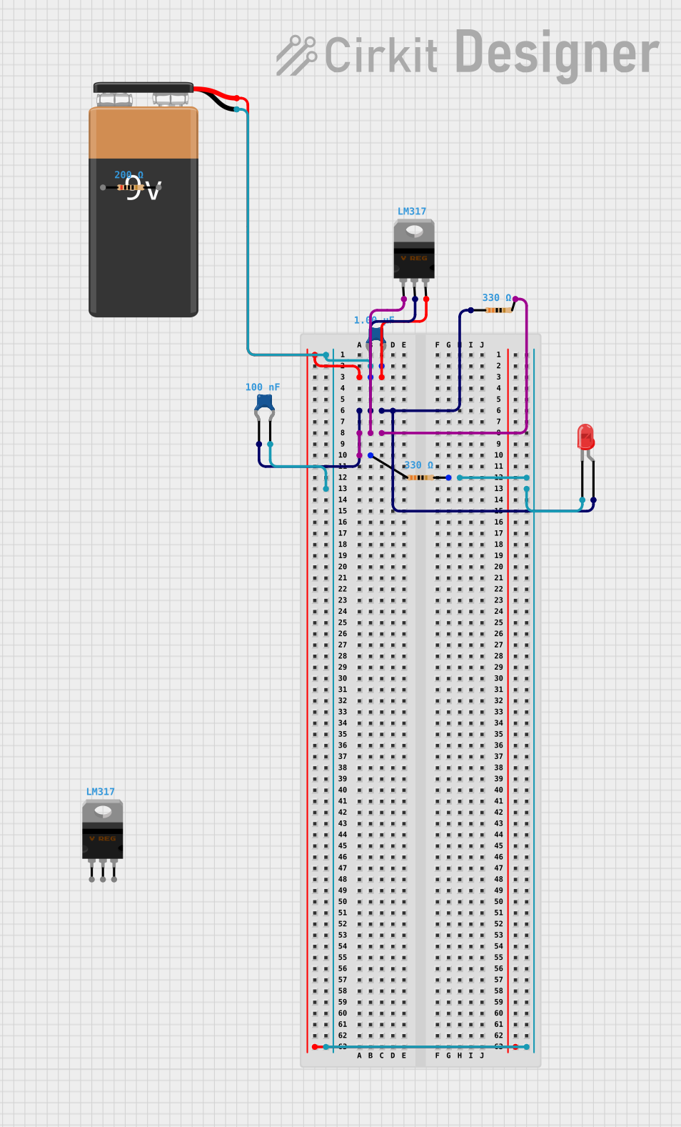
This circuit appears to be a simple LED driver with voltage regulation provided by an LM317 voltage regulator. The circuit uses a 9V battery as the power source. The LED is protected by a series resistor, and the voltage regulator is configured with a pair of resistors and capacitors to stabilize the output voltage. The capacitors are likely used for filtering purposes to provide a smooth DC output.
Component List
9V Battery
- Description: A standard 9V battery used as the power source for the circuit.
Resistor (200 Ohms)
- Description: A resistor with a resistance of 200 Ohms.
Resistor (330 Ohms)
- Description: A resistor with a resistance of 330 Ohms.
LED: Two Pin (red)
- Description: A red two-pin LED used as the load in the circuit.
LM317 Voltage Regulator
- Description: An adjustable 3-terminal positive voltage regulator used to maintain a stable output voltage.
Ceramic Capacitor (1 µF)
- Description: A ceramic capacitor with a capacitance of 1 microfarad (µF).
Ceramic Capacitor (0.1 µF)
- Description: A ceramic capacitor with a capacitance of 0.1 microfarads (µF).
Wiring Details
9V Battery
Negative terminal connected to:
- One terminal of the 1 µF ceramic capacitor.
- One terminal of the 0.1 µF ceramic capacitor.
- Pin2 of the 330 Ohms resistor.
- Cathode of the red LED.
Positive terminal connected to:
- V_in pin of the LM317 voltage regulator.
- One terminal of the 1 µF ceramic capacitor.
Resistor (200 Ohms)
- Not connected in the provided net list.
Resistor (330 Ohms)
Pin1 connected to:
- Adj pin of the LM317 voltage regulator.
- Pin2 of another 330 Ohms resistor.
Pin2 connected to:
- Negative terminal of the 9V battery.
- Cathode of the red LED.
- One terminal of the 1 µF ceramic capacitor.
- One terminal of the 0.1 µF ceramic capacitor.
LED: Two Pin (red)
Cathode connected to:
- Negative terminal of the 9V battery.
- Pin2 of the 330 Ohms resistor.
Anode connected to:
- One terminal of the 0.1 µF ceramic capacitor.
- Pin1 of another 330 Ohms resistor.
- V_out pin of the LM317 voltage regulator.
LM317 Voltage Regulator
Adj pin connected to:
- Pin1 of the 330 Ohms resistor.
- Pin2 of another 330 Ohms resistor.
V_out pin connected to:
- Anode of the red LED.
- One terminal of the 0.1 µF ceramic capacitor.
V_in pin connected to:
- Positive terminal of the 9V battery.
- One terminal of the 1 µF ceramic capacitor.
Ceramic Capacitor (1 µF)
One terminal connected to:
- Negative terminal of the 9V battery.
- V_in pin of the LM317 voltage regulator.
The other terminal is not connected in the provided net list.
Ceramic Capacitor (0.1 µF)
One terminal connected to:
- Negative terminal of the 9V battery.
- Cathode of the red LED.
- Pin2 of the 330 Ohms resistor.
The other terminal connected to:
- Anode of the red LED.
- Pin1 of another 330 Ohms resistor.
- V_out pin of the LM317 voltage regulator.
Documented Code
There is no code provided for any microcontrollers in the circuit. If code becomes available, it will be documented in this section.