Cirkit Designer
Your all-in-one circuit design IDE
Home /
Project Documentation
Arduino UNO Bluetooth-Enabled Flame Detection Alert System
Circuit Documentation
Summary of the Circuit
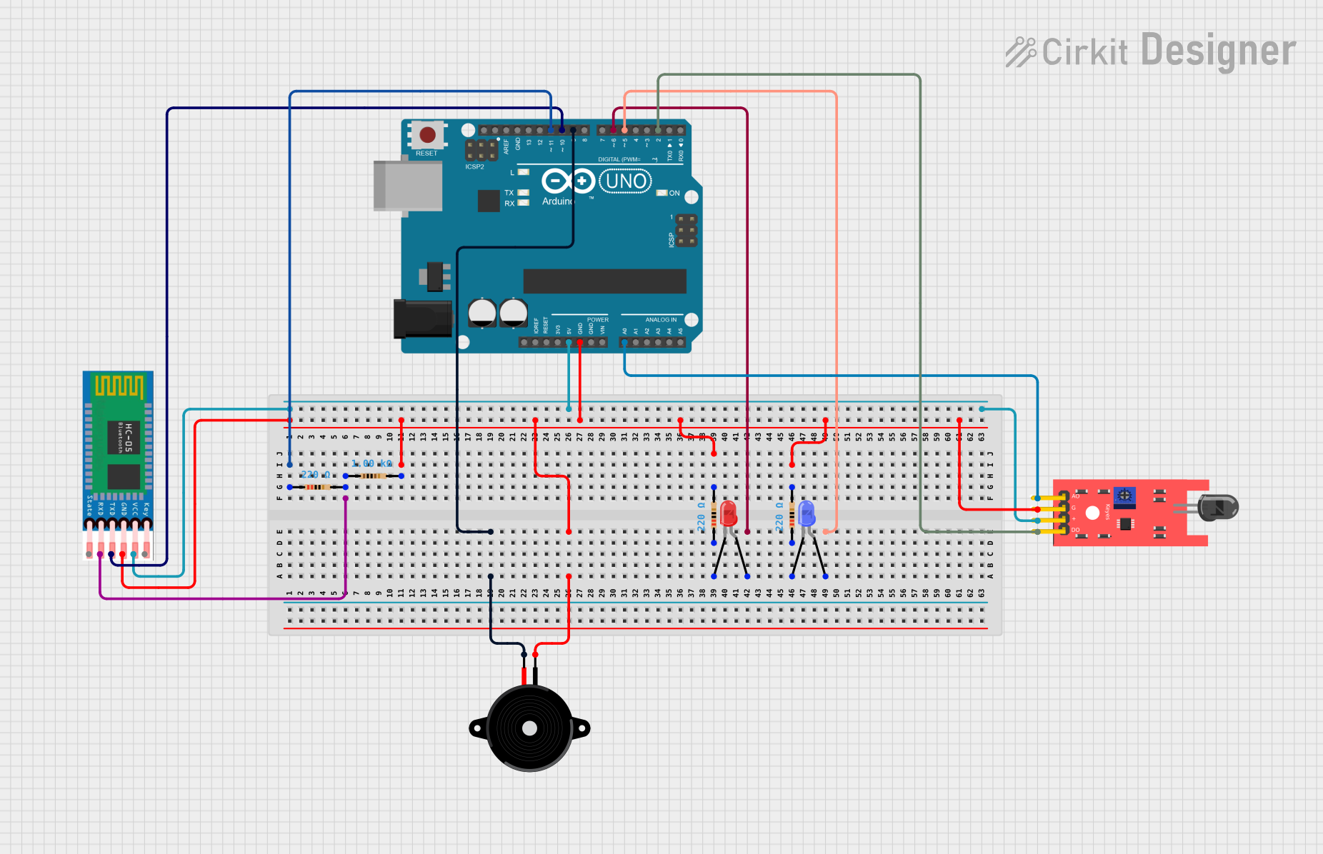
This circuit appears to be designed for a basic control and sensing application, utilizing an Arduino UNO as the central microcontroller. The circuit includes a Bluetooth module (HC-05) for wireless communication, a flame sensor for detecting fire or a high-temperature source, a piezo speaker for audio feedback, and two LEDs (red and blue) for visual indicators. The circuit also includes resistors for current limiting and pull-up/down configurations.
Component List
Arduino UNO
- Microcontroller board based on the ATmega328P
- It has 14 digital input/output pins, 6 analog inputs, a 16 MHz quartz crystal, a USB connection, a power jack, an ICSP header, and a reset button.
HC-05 Bluetooth Module
- Wireless communication module that can operate as either a master or slave.
- It has pins for enabling (EN), power supply (VCC), ground (GND), transmit (TXD), receive (RXD), and state (STATE).
KY-026 Flame Sensor
- Sensor module for detecting fire and flame wavelengths between 760 nm to 1100 nm.
- It has pins for analog output (A0), digital output (D0), ground (GND), and power supply (VCC).
Piezo Speaker
- An electronic device that can be used to produce sound or tones when an electrical signal is applied.
- It has two pins for electrical connection.
LED: Two Pin (red)
- A red light-emitting diode that emits red light when powered.
- It has two pins: anode and cathode.
LED: Two Pin (blue)
- A blue light-emitting diode that emits blue light when powered.
- It has two pins: anode and cathode.
Resistor (220 Ohms)
- A passive two-terminal electrical component that implements electrical resistance as a circuit element.
- It has two pins for electrical connection.
Resistor (1000 Ohms)
- A passive two-terminal electrical component with a resistance of 1000 Ohms.
- It has two pins for electrical connection.
Wiring Details
Arduino UNO
- D11 connected to Resistor (220 Ohms)
- GND connected to common ground net
- 5V connected to HC-05 (VCC) and KY-026 Flame Sensor (VCC)
- A0 connected to KY-026 Flame Sensor (A0)
- D10 connected to HC-05 (TXD)
- D2 connected to KY-026 Flame Sensor (D0)
- D9 connected to Piezo Speaker
- D6 connected to LED: Two Pin (red) (anode)
- D5 connected to LED: Two Pin (blue) (anode)
HC-05 Bluetooth Module
- RXD connected to Resistor (1000 Ohms)
- GND connected to common ground net
- VCC connected to Arduino UNO (5V)
- TXD connected to Arduino UNO (D10)
KY-026 Flame Sensor
- A0 connected to Arduino UNO (A0)
- GND connected to common ground net
- VCC connected to Arduino UNO (5V)
- D0 connected to Arduino UNO (D2)
Piezo Speaker
- One pin connected to Arduino UNO (D9)
- Other pin connected to common ground net
LED: Two Pin (red)
- Anode connected to Arduino UNO (D6)
- Cathode connected to Resistor (220 Ohms)
LED: Two Pin (blue)
- Anode connected to Arduino UNO (D5)
- Cathode connected to Resistor (220 Ohms)
Resistor (220 Ohms)
- One pin connected to LED: Two Pin (red) (cathode)
- Other pin connected to common ground net
Resistor (1000 Ohms)
- One pin connected to HC-05 (RXD)
- Other pin connected to common ground net
Documented Code
Arduino UNO Code (sketch.ino)
void setup() {
  // put your setup code here, to run once:

}

void loop() {
  // put your main code here, to run repeatedly:

}
Additional Notes
- The provided code for the Arduino UNO is a template with empty setup and loop functions. Actual functionality needs to be implemented based on the requirements of the circuit's application.
- The documentation file for the Arduino UNO code is empty and does not contain any additional information.