
Arduino UNO Coin Counting Machine with IR Sensors and 16x2 I2C LCD Display
View and Edit Project In Cirkit Designer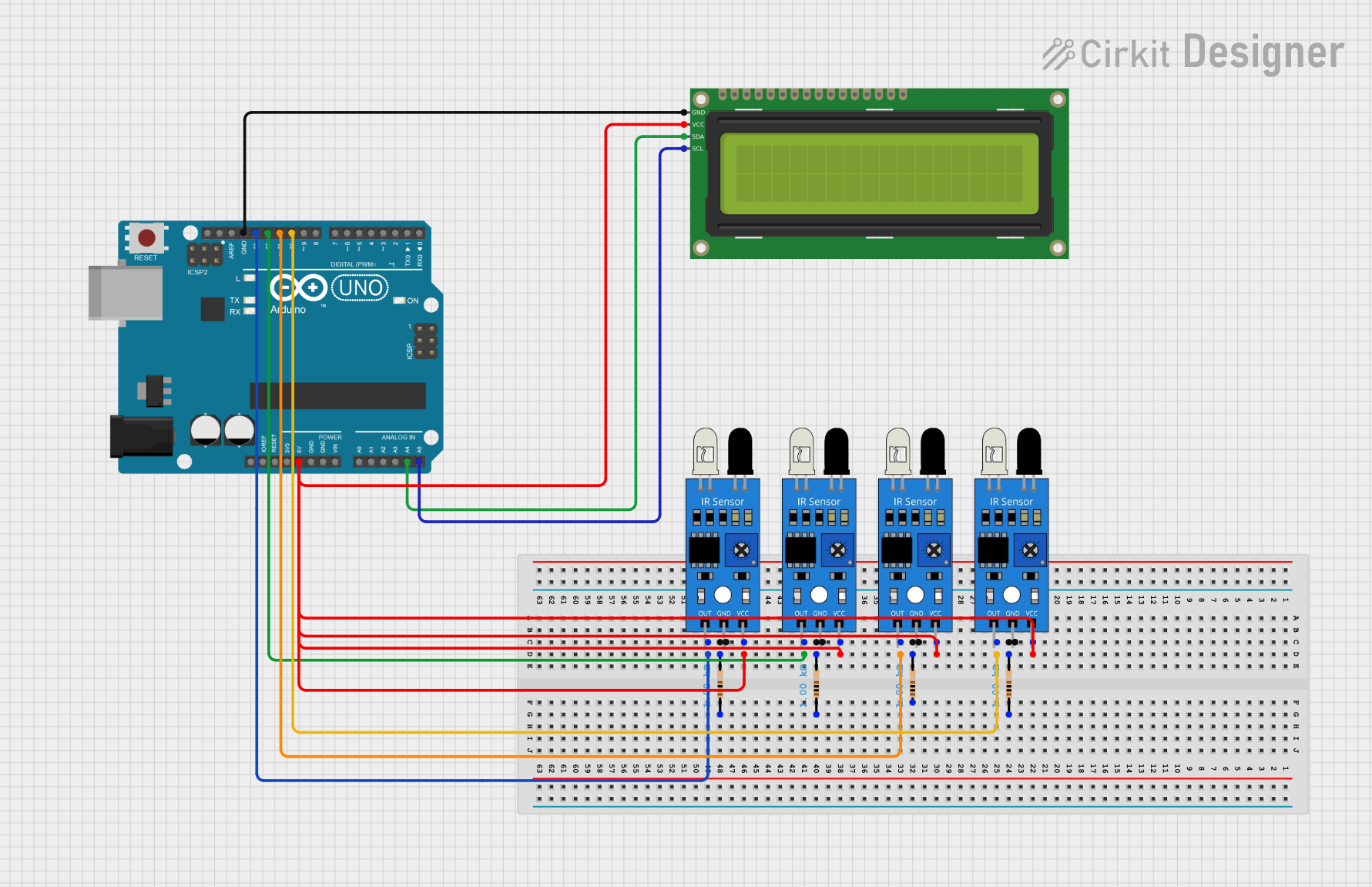
Circuit Documentation
Summary
This circuit is a coin counting machine that uses multiple IR sensors to detect coins and displays the count on a 16x2 I2C LCD. The circuit is controlled by an Arduino UNO microcontroller. The coin values detected are 1 peso, 5 peso, 10 peso, and 20 peso.
Component List
16x2 I2C LCD
- Description: A 16x2 character LCD display with I2C interface.
- Pins: GND, VCC, SDA, SCL
Arduino UNO
- Description: A microcontroller board based on the ATmega328P.
- Pins: UNUSED, IOREF, Reset, 3.3V, 5V, GND, Vin, A0, A1, A2, A3, A4, A5, SCL, SDA, AREF, D13, D12, D11, D10, D9, D8, D7, D6, D5, D4, D3, D2, D1, D0
IR Sensor
- Description: Infrared sensor used to detect the presence of coins.
- Pins: out, gnd, vcc
Resistor
- Description: A resistor with a resistance of 1000 Ohms.
- Pins: pin1, pin2
- Properties: Resistance: 1000 Ohms
Wiring Details
16x2 I2C LCD
- GND connected to GND of Arduino UNO
- VCC connected to 5V of Arduino UNO
- SDA connected to A4 of Arduino UNO
- SCL connected to A5 of Arduino UNO
Arduino UNO
- 5V connected to VCC of all IR Sensors and 16x2 I2C LCD
- GND connected to GND of 16x2 I2C LCD
- D10 connected to out of one IR Sensor
- D11 connected to out of another IR Sensor
- D12 connected to out of another IR Sensor
- D13 connected to out of another IR Sensor
- A4 connected to SDA of 16x2 I2C LCD
- A5 connected to SCL of 16x2 I2C LCD
IR Sensor 1
- vcc connected to 5V of Arduino UNO
- gnd connected to pin2 of a Resistor
- out connected to D10 of Arduino UNO
IR Sensor 2
- vcc connected to 5V of Arduino UNO
- gnd connected to pin2 of a Resistor
- out connected to D11 of Arduino UNO
IR Sensor 3
- vcc connected to 5V of Arduino UNO
- gnd connected to pin2 of a Resistor
- out connected to D12 of Arduino UNO
IR Sensor 4
- vcc connected to 5V of Arduino UNO
- gnd connected to pin2 of a Resistor
- out connected to D13 of Arduino UNO
Resistor 1
- pin1 connected to GND
- pin2 connected to gnd of IR Sensor 1
Resistor 2
- pin1 connected to GND
- pin2 connected to gnd of IR Sensor 2
Resistor 3
- pin1 connected to GND
- pin2 connected to gnd of IR Sensor 3
Resistor 4
- pin1 connected to GND
- pin2 connected to gnd of IR Sensor 4
Code Documentation
Arduino UNO Code
/*
 * Coin Counting Machine
 * This code reads inputs from IR sensors to detect coins and displays the
 * count on a 16x2 I2C LCD. The coin values are 1 peso, 5 peso, 10 peso, and
 * 20 peso.
 */

#include <Wire.h>
#include <LiquidCrystal_I2C.h>

// Initialize the LCD, set the LCD address to 0x27 for a 16 chars and 2 line
LiquidCrystal_I2C lcd(0x27, 16, 2);

// IR sensor pins
const int irSensor1 = 13;
const int irSensor2 = 12;
const int irSensor3 = 11;
const int irSensor4 = 10;

// Coin counts
int count1Peso = 0;
int count5Peso = 0;
int count10Peso = 0;
int count20Peso = 0;

void setup() {
  // Initialize the LCD
  lcd.begin();
  lcd.backlight();
  lcd.setCursor(0, 0);
  lcd.print("Coin Counter");

  // Initialize IR sensor pins
  pinMode(irSensor1, INPUT);
  pinMode(irSensor2, INPUT);
  pinMode(irSensor3, INPUT);
  pinMode(irSensor4, INPUT);
}

void loop() {
  // Check IR sensors
  if (digitalRead(irSensor1) == LOW) {
    count1Peso++;
    displayCount();
    delay(500); // Debounce delay
  }
  if (digitalRead(irSensor2) == LOW) {
    count5Peso++;
    displayCount();
    delay(500); // Debounce delay
  }
  if (digitalRead(irSensor3) == LOW) {
    count10Peso++;
    displayCount();
    delay(500); // Debounce delay
  }
  if (digitalRead(irSensor4) == LOW) {
    count20Peso++;
    displayCount();
    delay(500); // Debounce delay
  }
}

void displayCount() {
  lcd.clear();
  lcd.setCursor(0, 0);
  lcd.print("1P: ");
  lcd.print(count1Peso);
  lcd.setCursor(8, 0);
  lcd.print("5P: ");
  lcd.print(count5Peso);
  lcd.setCursor(0, 1);
  lcd.print("10P: ");
  lcd.print(count10Peso);
  lcd.setCursor(8, 1);
  lcd.print("20P: ");
  lcd.print(count20Peso);
}
IR Sensor Code
void setup() {
  // put your setup code here, to run once:

}

void loop() {
  // put your main code here, to run repeatedly:

}
This concludes the documentation for the coin counting machine circuit.