
Arduino UNO-Based Health Monitoring System with Heart Pulse Sensor and MPU-6050
View and Edit Project In Cirkit Designer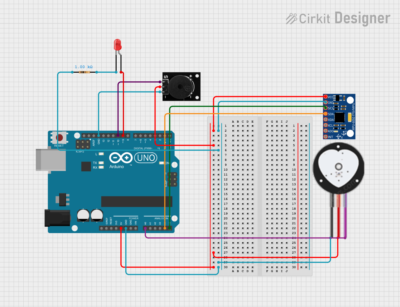
Circuit Documentation
Summary
This circuit involves an Arduino UNO microcontroller interfacing with several components including a Heart Pulse Sensor, a Passive Buzzer, an MPU-6050 accelerometer and gyroscope, a red LED, and a resistor. The circuit is designed to read heart pulse data, detect motion, and provide audio and visual feedback.
Component List
Arduino UNO
- Description: A microcontroller board based on the ATmega328P.
- Pins: UNUSED, IOREF, Reset, 3.3V, 5V, GND, Vin, A0, A1, A2, A3, A4, A5, SCL, SDA, AREF, D13, D12, D11, D10, D9, D8, D7, D6, D5, D4, D3, D2, D1, D0
Resistor
- Description: A passive electrical component that implements electrical resistance as a circuit element.
- Pins: pin1, pin2
- Properties:
- Resistance: 1000 Ohms
Heart Pulse Sensor
- Description: A sensor used to measure heart rate.
- Pins: GND, VCC, SIGNAL
Passive Buzzer
- Description: An audio signaling device.
- Pins: S output signal, +VCC, GND
MPU-6050
- Description: A 6-axis motion tracking device that combines a 3-axis gyroscope and a 3-axis accelerometer.
- Pins: VCC, GND, SCL, SDA, XDA, XCL, AD0, INT
LED: Two Pin (red)
- Description: A red light-emitting diode.
- Pins: cathode, anode
Wiring Details
Arduino UNO
5V is connected to:
- VCC of MPU-6050
- +VCC of Passive Buzzer
- VCC of Heart Pulse Sensor
GND is connected to:
- GND of MPU-6050
- pin1 of Resistor
- GND of Heart Pulse Sensor
- GND of Passive Buzzer
A0 is connected to:
- SIGNAL of Heart Pulse Sensor
A4 is connected to:
- SDA of MPU-6050
A5 is connected to:
- SCL of MPU-6050
D10 is connected to:
- S output signal of Passive Buzzer
D9 is connected to:
- anode of LED: Two Pin (red)
Resistor
pin1 is connected to:
- GND of Arduino UNO
pin2 is connected to:
- cathode of LED: Two Pin (red)
Heart Pulse Sensor
GND is connected to:
- GND of Arduino UNO
VCC is connected to:
- 5V of Arduino UNO
SIGNAL is connected to:
- A0 of Arduino UNO
Passive Buzzer
S output signal is connected to:
- D10 of Arduino UNO
+VCC is connected to:
- 5V of Arduino UNO
GND is connected to:
- GND of Arduino UNO
MPU-6050
VCC is connected to:
- 5V of Arduino UNO
GND is connected to:
- GND of Arduino UNO
SDA is connected to:
- A4 of Arduino UNO
SCL is connected to:
- A5 of Arduino UNO
LED: Two Pin (red)
anode is connected to:
- D9 of Arduino UNO
cathode is connected to:
- pin2 of Resistor
Documented Code
Arduino UNO Code
void setup() {
  // put your setup code here, to run once:

}

void loop() {
  // put your main code here, to run repeatedly:

}
This code is a basic template for the Arduino UNO. The setup() function is where you initialize settings, and the loop() function runs continuously after the setup is complete. You can add your specific logic to read sensor data, control the buzzer, and manage the LED within these functions.