
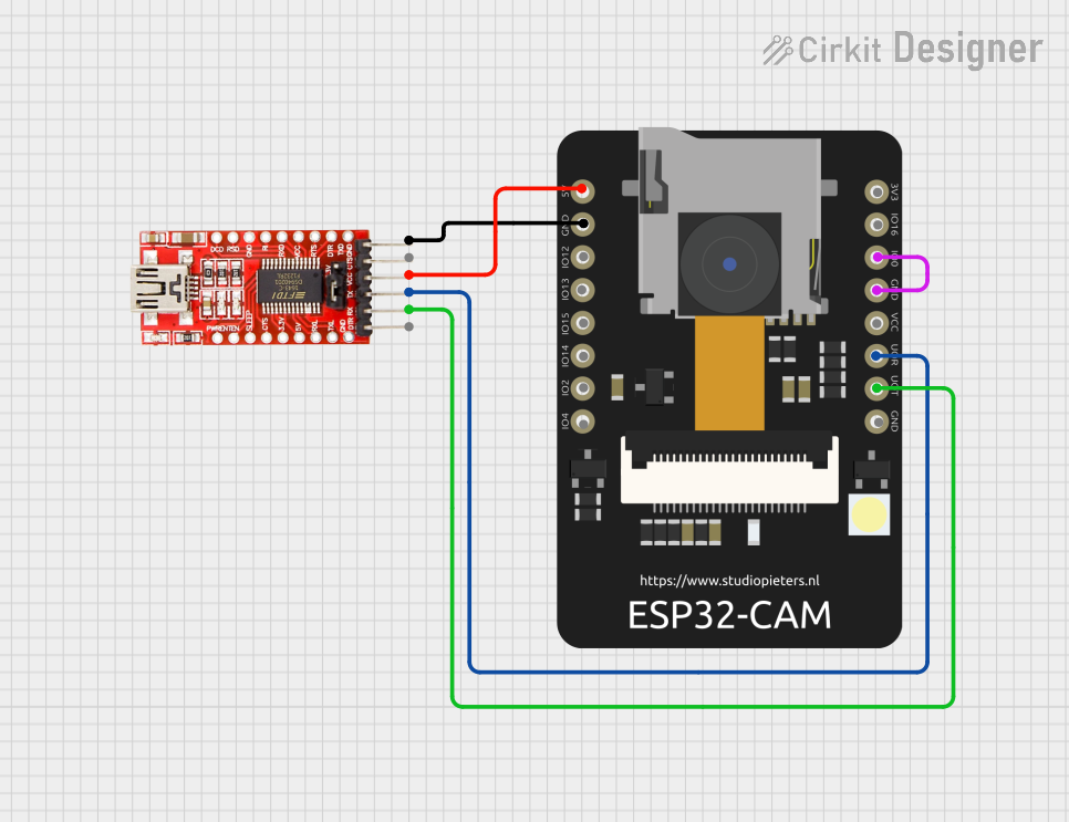
Circuit Documentation
Summary of the Circuit
The circuit described in the provided inputs consists of an ESP32 CAM module interfaced with an FTDI Programmer. The ESP32 CAM is a small-sized camera module that comes with an ESP32-S chip onboard. It is designed for IoT applications and supports image Wi-Fi upload. The FTDI Programmer is used to program devices like the ESP32 CAM through a serial interface.
The circuit allows for programming the ESP32 CAM using the FTDI Programmer via a serial connection. Additionally, the ESP32 CAM is powered through the FTDI Programmer, and a direct connection between GPIO0 and GND on the ESP32 CAM suggests a boot mode configuration for programming.
Component List
ESP32 CAM
- Pins: 5V, GND, GPIO12, GPIO13, GPIO15, GPIO14, GPIO2, GPIO4, 3.3V, GPIO16, GPIO0, 3.3V / 5V / P_OUT, GPIO3 / RX, GPIO1 / TX
- Description: A camera module with an onboard ESP32-S chip, suitable for IoT applications with image capture and Wi-Fi capabilities.
FTDI Programmer
- Pins: DTR, RX, TX, VCC, CTS, GND
- Description: A USB to serial interface device used to program microcontrollers like the ESP32 CAM.
Wiring Details
ESP32 CAM
- 5V connected to FTDI Programmer VCC
- GND connected to FTDI Programmer GND and ESP32 CAM GPIO0 (for boot mode configuration)
- GPIO3 / RX connected to FTDI Programmer TX
- GPIO1 / TX connected to FTDI Programmer RX
FTDI Programmer
- VCC connected to ESP32 CAM 5V
- GND connected to ESP32 CAM GND
- TX connected to ESP32 CAM GPIO3 / RX
- RX connected to ESP32 CAM GPIO1 / TX
Documented Code
No code has been provided for the microcontrollers in the circuit. Therefore, this section is not applicable for the current documentation. When code is available, it should be documented here with explanations for each function and routine, including setup and loop functions for microcontrollers like the ESP32 CAM.