
Arduino UNO Controlled Traffic Light System with Touch Sensor Interaction
View and Edit Project In Cirkit Designer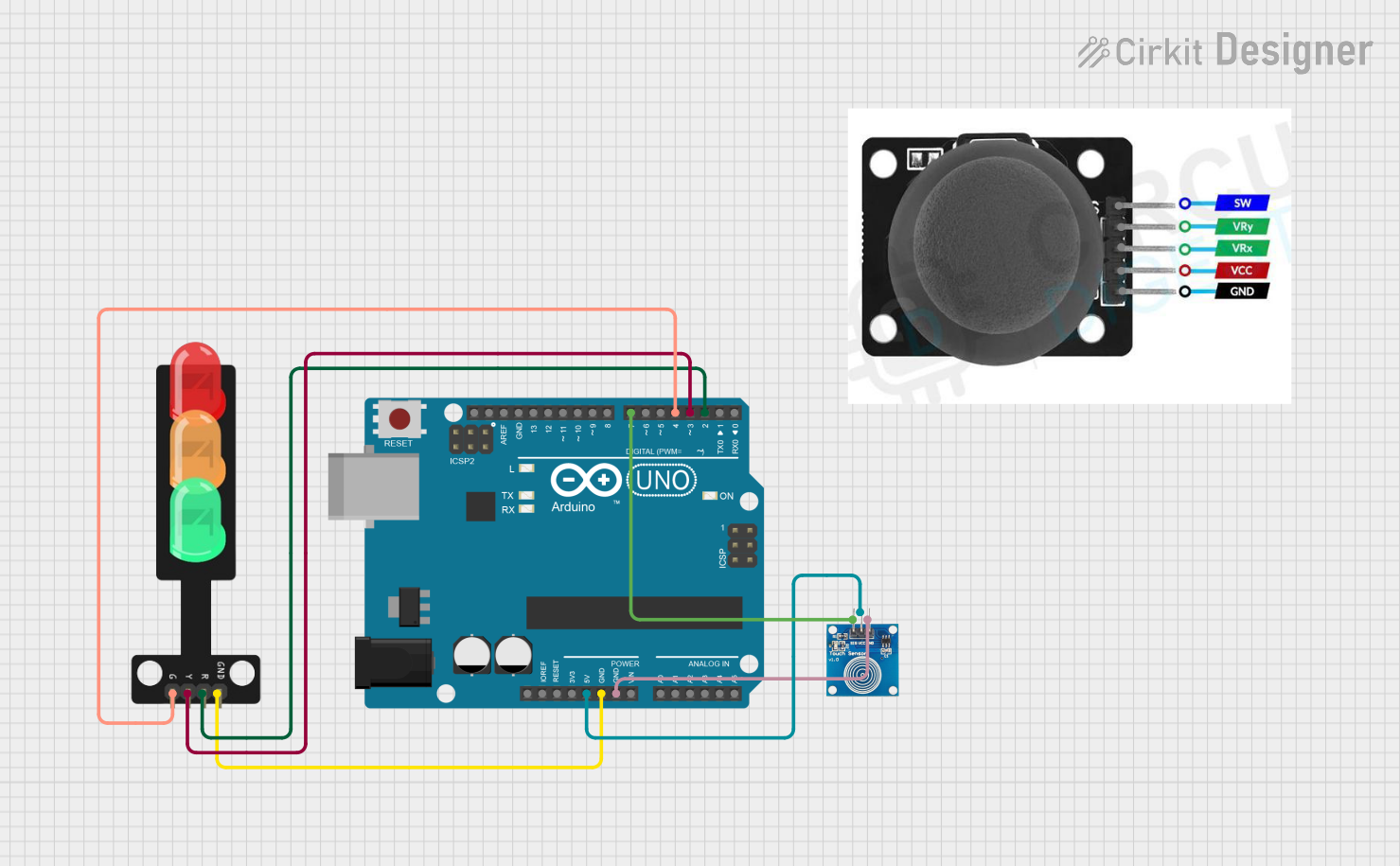
Traffic Light Control System Documentation
Summary
This document describes a traffic light control system designed using an Arduino UNO microcontroller. The system utilizes a touch sensor to cycle through the traffic light states, which include Red, Yellow, and Green LEDs. The touch sensor allows the user to change the state of the traffic lights with each press, cycling through Red, Yellow, Green, and then turning all LEDs off before repeating the cycle.
Component List
Arduino UNO
- Description: A microcontroller board based on the ATmega328P.
- Pins: UNUSED, IOREF, Reset, 3.3V, 5V, GND, Vin, A0-A5, SCL, SDA, AREF, D0-D13.
Traffic Light
- Description: A module with three LEDs representing a traffic light system.
- Pins: Green, Yellow, Red, GND.
Joystick Module
- Description: An input device that provides two-dimensional control with a vertical and horizontal axis.
- Pins: SW, VRY, VRX, VCC, GND.
Touch Sensor
- Description: A sensor that detects touch or proximity.
- Pins: IO, VCC, GND.
Wiring Details
Arduino UNO
- 5V connected to Touch Sensor VCC.
- GND connected to Traffic Light GND and Touch Sensor GND.
- D7 connected to Touch Sensor IO.
- D4 connected to Traffic Light Green.
- D3 connected to Traffic Light Yellow.
- D2 connected to Traffic Light Red.
Traffic Light
- Green connected to Arduino UNO D4.
- Yellow connected to Arduino UNO D3.
- Red connected to Arduino UNO D2.
- GND connected to Arduino UNO GND.
Joystick Module
- Note: The joystick module is not included in the wiring details as it is not connected in the provided net list.
Touch Sensor
- IO connected to Arduino UNO D7.
- VCC connected to Arduino UNO 5V.
- GND connected to Arduino UNO GND.
Documented Code
/*
 * This Arduino sketch controls a traffic light system using a touch sensor.
 * The traffic light has three LEDs: Green, Yellow, and Red.
 * The touch sensor cycles through the following states with each press:
 * - First press: Red LED turns on
 * - Second press: Yellow LED turns on
 * - Third press: Green LED turns on
 * - Fourth press: All LEDs turn off
 * - The cycle repeats with each subsequent press
 */

// Pin definitions
const int greenPin = 4;
const int yellowPin = 3;
const int redPin = 2;
const int touchPin = 7;

// State variable to keep track of the current LED state
int state = 0;

void setup() {
  // Initialize the digital pins as outputs
  pinMode(greenPin, OUTPUT);
  pinMode(yellowPin, OUTPUT);
  pinMode(redPin, OUTPUT);
  // Initialize the touch sensor pin as input
  pinMode(touchPin, INPUT);
}

void loop() {
  // Read the touch sensor value
  int touchValue = digitalRead(touchPin);
  // Check if the touch sensor is pressed
  if (touchValue == HIGH) {
    // Debounce delay
    delay(50);
    // Wait for the touch sensor to be released
    while (digitalRead(touchPin) == HIGH);
    // Cycle through the states
    state = (state + 1) % 4;
    // Update the LEDs based on the current state
    switch (state) {
      case 0:
        digitalWrite(redPin, HIGH);
        digitalWrite(yellowPin, LOW);
        digitalWrite(greenPin, LOW);
        break;
      case 1:
        digitalWrite(redPin, LOW);
        digitalWrite(yellowPin, HIGH);
        digitalWrite(greenPin, LOW);
        break;
      case 2:
        digitalWrite(redPin, LOW);
        digitalWrite(yellowPin, LOW);
        digitalWrite(greenPin, HIGH);
        break;
      case 3:
        digitalWrite(redPin, LOW);
        digitalWrite(yellowPin, LOW);
        digitalWrite(greenPin, LOW);
        break;
    }
    // Small delay to avoid multiple detections
    delay(200);
  }
}
This code is designed to be uploaded to the Arduino UNO microcontroller. It sets up the necessary pins as inputs and outputs and contains the main loop that reads the touch sensor and cycles through the traffic light states.