
Wi-Fi Controlled Environmental Monitoring System with Dual Stepper Motor Valve Actuation
View and Edit Project In Cirkit Designer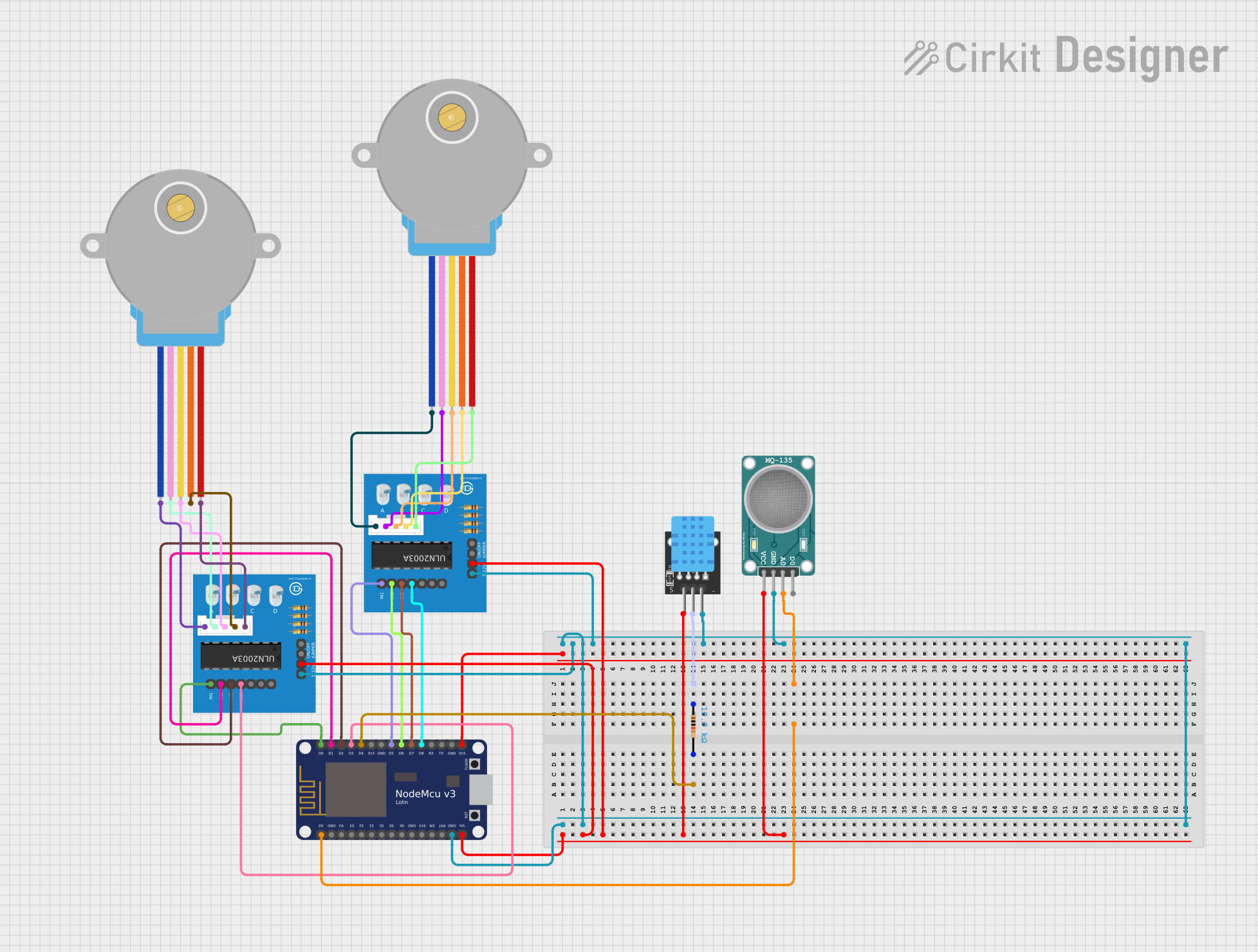
Circuit Documentation
Summary
The circuit in question is designed to control two 28BYJ-48 stepper motors using ULN2003A breakout boards and to monitor environmental conditions using an MQ-135 air quality sensor and a KY-015 DHT11 temperature and humidity sensor. The brain of the circuit is a NodeMCU V3 ESP8266 microcontroller, which is responsible for processing sensor data, controlling the stepper motors, and managing WiFi connectivity. A resistor is also included in the circuit for interfacing with the DHT11 sensor.
Component List
28BYJ-48 Stepper Motor
- Description: A small, 5-line, 4-phase stepper motor.
- Pins: BLUE, PINK, YELLOW, ORANGE, RED
ULN2003A Breakout Board
- Description: A breakout board for the ULN2003A transistor array, designed to drive stepper motors.
- Pins: In 1, In 2, In 3, In 4, In 5, In 6, In 7, 0V, +5V, ON/OFF jumper switch, BLUE wire, PINK wire, YELLOW wire, ORANGE wire, RED wire
MQ-135 Sensor Air Quality
- Description: A sensor for detecting a wide range of gases, including NH3, NOx, alcohol, benzene, smoke, and CO2.
- Pins: VCC, GND, A0, D0
NodeMCU V3 ESP8266
- Description: A WiFi module with an integrated ESP8266 microcontroller.
- Pins: A0, GND, VU, S3, S2, S1, SC, S0, SK, 3V3, EN, RST, Vin, D0, D1, D2, D3, D4, D5, D6, D7, D8, RX, TX
Resistor
- Description: A passive two-terminal electrical component that implements electrical resistance as a circuit element.
- Properties: 10,000 Ohms
KY-015 DHT11
- Description: A basic, ultra low-cost digital temperature and humidity sensor.
- Pins: 5V, S, GND
Wiring Details
28BYJ-48 Stepper Motor
- BLUE: Connected to the corresponding BLUE wire on the ULN2003A breakout board.
- PINK: Connected to the corresponding PINK wire on the ULN2003A breakout board.
- YELLOW: Connected to the corresponding YELLOW wire on the ULN2003A breakout board.
- ORANGE: Connected to the corresponding ORANGE wire on the ULN2003A breakout board.
- RED: Connected to the corresponding RED wire on the ULN2003A breakout board.
ULN2003A Breakout Board
- In 1 - In 4: Connected to the NodeMCU ESP8266 digital pins (D0-D8) for motor control.
- 0V: Connected to the NodeMCU ESP8266 GND pin.
- +5V: Connected to the NodeMCU ESP8266 Vin pin.
- BLUE wire - RED wire: Connected to the corresponding wires of the 28BYJ-48 stepper motors.
MQ-135 Sensor Air Quality
- VCC: Connected to the NodeMCU ESP8266 Vin pin.
- GND: Connected to the NodeMCU ESP8266 GND pin.
- A0: Connected to the NodeMCU ESP8266 A0 pin.
NodeMCU V3 ESP8266
- D0 - D8: Control signals for the ULN2003A breakout boards.
- A0: Receives analog input from the MQ-135 air quality sensor.
- Vin: Provides power to the ULN2003A breakout boards and the MQ-135 sensor.
- GND: Common ground for the circuit.
- 3V3: Not connected in this circuit.
Resistor
- pin1: Connected to the KY-015 DHT11 sensor signal pin.
- pin2: Connected to the NodeMCU ESP8266 D4 pin.
KY-015 DHT11
- 5V: Connected to the NodeMCU ESP8266 Vin pin.
- S: Connected to the NodeMCU ESP8266 D4 pin through a 10k Ohm resistor.
- GND: Connected to the NodeMCU ESP8266 GND pin.
Documented Code
NodeMCU V3 ESP8266 Code
#include <DHT.h>
#include <Stepper.h>
#include <ESP8266WiFi.h>

#define DHTPIN 2        // DHT11 data pin
#define DHTTYPE DHT11   // DHT11 sensor

// Stepper Motor Pins for Motor 1 (right valve)
#define IN1_R 8
#define IN2_R 9
#define IN3_R 10
#define IN4_R 11

// Stepper Motor Pins for Motor 2 (left valve)
#define IN1_L 4
#define IN2_L 5
#define IN3_L 6
#define IN4_L 7

// MQ135 Gas Sensor Pin
#define MQ135_PIN A0

// Stepper Motor configurations
const int STEPS_PER_REV = 2048; // Steps per revolution
Stepper motorRight(STEPS_PER_REV, IN1_R, IN2_R, IN3_R, IN4_R);
Stepper motorLeft(STEPS_PER_REV, IN1_L, IN2_L, IN3_L, IN4_L);

// DHT11 Sensor Setup
DHT dht(DHTPIN, DHTTYPE);

// WiFi Credentials
const char* ssid = "Your_SSID";
const char* password = "Your_PASSWORD";

float temperature;
int humidity;
int mq135Value;

// Steps for opening and closing the valve (30 degrees rotation)
const int valveOpenSteps = 171;

// Valve State Tracking
bool rightValveOpen = false;
bool leftValveOpen = false;

void setup() {
  Serial.begin(9600);

  // Initialize DHT11 sensor
  dht.begin();

  // Initialize stepper motors
  motorRight.setSpeed(10);
  motorLeft.setSpeed(10);

  // Initialize MQ135 sensor
  pinMode(MQ135_PIN, INPUT);

  // Initialize WiFi connection
  connectToWiFi();
}

void loop() {
  // Read temperature and humidity from DHT11
  temperature = dht.readTemperature();
  humidity = dht.readHumidity();

  // Read gas value from MQ135
  mq135Value = analogRead(MQ135_PIN);

  // Output sensor values to the serial monitor
  Serial.print("Temperature: ");
  Serial.print(temperature);
  Serial.println(" C");

  Serial.print("Humidity: ");
  Serial.print(humidity);
  Serial.println(" %");

  Serial.print("MQ135 Gas Sensor Value: ");
  Serial.println(mq135Value);

  // Valve control logic based on temperature
  if (temperature >= 10 && temperature <= 35) {
    Serial.println("Normal temperature, opening right valve...");

    if (!rightValveOpen) {
      closeLeftValve();   // Ensure left valve is closed
      openRightValve();   // Open right valve
    }

  } else {
    Serial.println("Abnormal temperature, opening left valve...");

    if (!leftValveOpen) {
      closeRightValve();  // Ensure right valve is closed
      openLeftValve();    // Open left valve
    }
  }

  delay(2000); // Delay for 2 seconds before next reading
}

// Function to connect to WiFi
void connectToWiFi() {
  Serial.println("Connecting to WiFi...");
  WiFi.begin(ssid, password);

  while (WiFi.status() != WL_CONNECTED) {
    delay(1000);
    Serial.println("Connecting...");
  }

  Serial.println("Connected to WiFi");
}

// Function to open the right valve (rotate 30 degrees)
void openRightValve() {
  motorRight.step(valveOpenSteps);
  rightValveOpen = true;
  Serial.println("Right valve opened (30 degrees).");
}

// Function to close the right valve (rotate back to 0 degrees)
void closeRightValve() {
  if (rightValveOpen) {
    motorRight.step(-valveOpenSteps);
    rightValveOpen = false;
    Serial.println("Right valve closed (0 degrees).");
  }
}

// Function to open the left valve (rotate 30 degrees)
void openLeftValve() {
  motorLeft.step(valveOpenSteps);
  leftValveOpen = true;
  Serial.println("Left valve opened (30 degrees).");
}

// Function to close the left valve (rotate back to 0 degrees)
void closeLeftValve() {
  if (leftValveOpen) {
    motorLeft.step(-valveOpenSteps);
    leftValveOpen = false;
    Serial.println("Left valve closed (0 degrees).");
  }
}
Note: The code provided is for the NodeMCU V3 ESP8266 microcontroller and includes the logic for reading sensor data, controlling stepper motors, and managing WiFi connectivity. The code is structured with setup and loop functions, as well as additional functions for WiFi connection and valve control.