
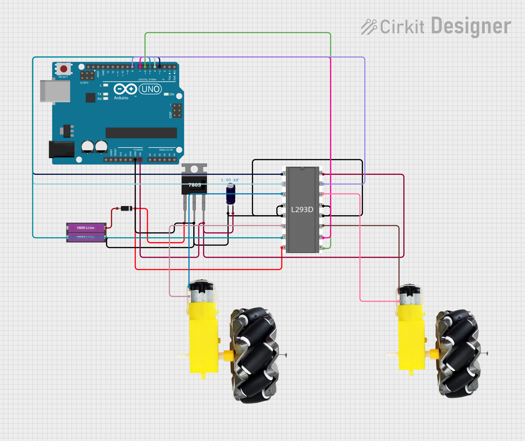
Circuit Documentation
Summary
This circuit is designed to control a smart car using an Arduino UNO microcontroller and an L293D motor driver. The car's movement can be controlled via serial communication, which is handled by the Arduino UNO. The circuit includes a power supply consisting of two 18650 Li-ion batteries, a 7805 voltage regulator, and a diode for reverse voltage protection. An electrolytic capacitor is used for voltage smoothing. The motors and wheels are driven by the L293D motor driver, which receives control signals from the Arduino UNO.
Component List
Arduino UNO
- Microcontroller board based on the ATmega328P
- Used for controlling the smart car's motors and handling serial communication
L293D Motor Driver
- Quadruple high-current half-H driver
- Used to drive the motors of the smart car
18650 Li-ion Battery x 2
- Rechargeable battery providing power to the circuit
7805 Voltage Regulator
- Voltage regulator that outputs a stable 5V from a higher voltage input
Diode
- Used for reverse voltage protection
Electrolytic Capacitor
- Capacitance: 1000 Farads
- Used for voltage smoothing in the power supply
Motor and Wheels (x2)
- Actuators for the smart car's movement
Wiring Details
Arduino UNO
GNDconnected to the common ground netVinconnected to the positive side of the Electrolytic Capacitor- Digital pins
D3toD8connected to the L293D motor driver control inputs
L293D Motor Driver
gndpins connected to the common ground netvssconnected to the positive side of the Electrolytic Capacitorvsconnected to the 7805Voutenable 1,input 1,input 2,enable 2,input 3, andinput 4connected to Arduino UNO digital pinsD3toD8output 1,output 2,output 3, andoutput 4connected to the respective motor and wheels
18650 Li-ion Battery x 2
+connected to the anode of the Diode-connected to the common ground net
7805 Voltage Regulator
Vinconnected to the cathode of the DiodeGndconnected to the common ground netVoutconnected to thevsof the L293D motor driver
Diode
anodeconnected to the positive terminal of the 18650 Li-ion Battery x 2cathodeconnected to theVinof the 7805 Voltage Regulator
Electrolytic Capacitor
+connected to theVinof the Arduino UNO andvssof the L293D motor driver-connected to the common ground net
Motor and Wheels
- Two sets of
vccandGNDconnected to theoutput 1,output 2,output 3, andoutput 4of the L293D motor driver
Documented Code
/*
 * Smartcar with VC-02 AI Thinker
 * This Arduino sketch controls a smart car with motor drivers and a VC-02 module.
 * The car can be controlled via serial communication with the VC-02 module.
 */

// Pin definitions
const int motorEnable1 = 3;
const int motorInput1 = 4;
const int motorInput2 = 5;
const int motorEnable2 = 6;
const int motorInput3 = 7;
const int motorInput4 = 8;

void setup() {
  // Initialize serial communication
  Serial.begin(9600);

  // Initialize motor control pins
  pinMode(motorEnable1, OUTPUT);
  pinMode(motorInput1, OUTPUT);
  pinMode(motorInput2, OUTPUT);
  pinMode(motorEnable2, OUTPUT);
  pinMode(motorInput3, OUTPUT);
  pinMode(motorInput4, OUTPUT);

  // Set initial motor states
  digitalWrite(motorEnable1, LOW);
  digitalWrite(motorInput1, LOW);
  digitalWrite(motorInput2, LOW);
  digitalWrite(motorEnable2, LOW);
  digitalWrite(motorInput3, LOW);
  digitalWrite(motorInput4, LOW);
}

void loop() {
  // Check if data is available from VC-02 module
  if (Serial.available() > 0) {
    char command = Serial.read();
    handleCommand(command);
  }
}

void handleCommand(char command) {
  switch (command) {
    case 'F': // Move forward
      digitalWrite(motorEnable1, HIGH);
      digitalWrite(motorInput1, HIGH);
      digitalWrite(motorInput2, LOW);
      digitalWrite(motorEnable2, HIGH);
      digitalWrite(motorInput3, HIGH);
      digitalWrite(motorInput4, LOW);
      break;
    case 'B': // Move backward
      digitalWrite(motorEnable1, HIGH);
      digitalWrite(motorInput1, LOW);
      digitalWrite(motorInput2, HIGH);
      digitalWrite(motorEnable2, HIGH);
      digitalWrite(motorInput3, LOW);
      digitalWrite(motorInput4, HIGH);
      break;
    case 'L': // Turn left
      digitalWrite(motorEnable1, HIGH);
      digitalWrite(motorInput1, LOW);
      digitalWrite(motorInput2, HIGH);
      digitalWrite(motorEnable2, HIGH);
      digitalWrite(motorInput3, HIGH);
      digitalWrite(motorInput4, LOW);
      break;
    case 'R': // Turn right
      digitalWrite(motorEnable1, HIGH);
      digitalWrite(motorInput1, HIGH);
      digitalWrite(motorInput2, LOW);
      digitalWrite(motorEnable2, HIGH);
      digitalWrite(motorInput3, LOW);
      digitalWrite(motorInput4, HIGH);
      break;
    case 'S': // Stop
      digitalWrite(motorEnable1, LOW);
      digitalWrite(motorEnable2, LOW);
      break;
    default:
      // Unknown command
      break;
  }
}
This code is responsible for interpreting commands received via serial communication and controlling the motors accordingly. The commands 'F', 'B', 'L', 'R', and 'S' correspond to forward, backward, left, right, and stop movements of the smart car.