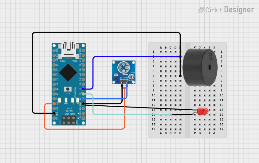
Arduino Nano-Based Touch-Activated Buzzer and LED Indicator

Circuit Documentation
Summary of the Circuit
This circuit is designed around an Arduino Nano microcontroller and includes a buzzer, a red two-pin LED, and a touch sensor. The Arduino Nano serves as the central processing unit, controlling the buzzer and LED based on input from the touch sensor. The circuit is powered by the Arduino Nano's 5V output, which also powers the touch sensor. The buzzer and LED are connected to digital pins on the Arduino Nano and are controlled through these pins.
Component List
Arduino Nano
- Description: A compact microcontroller board based on the ATmega328P.
- Pins: D1/TX, D0/RX, RESET, GND, D2, D3, D4, D5, D6, D7, D8, D9, D10, D11/MOSI, D12/MISO, VIN, 5V, A7, A6, A5, A4, A3, A2, A1, A0, AREF, 3V3, D13/SCK.
Buzzer
- Description: An electromechanical component that emits sound when an electrical signal is applied.
- Pins: PIN, GND.
LED: Two Pin (red)
- Description: A red light-emitting diode that emits light when current flows through it.
- Pins: cathode, anode.
Touch Sensor
- Description: A sensor that detects touch or proximity.
- Pins: IO, VCC, GND.
Wiring Details
Arduino Nano
- D4: Connected to the buzzer's PIN.
- GND: Common ground shared with the buzzer, LED, and touch sensor.
- D3: Connected to the anode of the red LED.
- D2: Connected to the IO pin of the touch sensor.
- 5V: Provides power to the VCC pin of the touch sensor.
Buzzer
- PIN: Connected to D4 on the Arduino Nano.
- GND: Connected to GND on the Arduino Nano.
LED: Two Pin (red)
- Anode: Connected to D3 on the Arduino Nano.
- Cathode: Needs to be connected to GND (not specified in the net list, but necessary for operation).
Touch Sensor
- IO: Connected to D2 on the Arduino Nano.
- VCC: Connected to 5V on the Arduino Nano.
- GND: Connected to GND on the Arduino Nano.
Documented Code
The code provided is for the Arduino Nano microcontroller. It is written in Arduino's implementation of C/C++ and is intended to be compiled and uploaded to the Arduino Nano using the Arduino IDE or a compatible toolchain.
sketch.ino
void setup() {
  // put your setup code here, to run once:

}

void loop() {
  // put your main code here, to run repeatedly:

}
The setup() function is called once when the microcontroller is reset or powered on. It is used to initialize the pins and set up the initial state of the circuit. The loop() function is called repeatedly and contains the main logic of the program.
Currently, the code is a template with no specific functionality implemented. To control the buzzer, LED, and read the touch sensor, code needs to be added to the setup() and loop() functions to initialize the pins as outputs or inputs and to write or read from those pins.
documentation.txt
The second file, documentation.txt, is empty and does not contain any code or comments. It is likely intended to be a placeholder for additional documentation or notes related to the code.