
NodeMCU ESP8266 Based Smart Light Control with MQTT and LDR Sensor
View and Edit Project In Cirkit Designer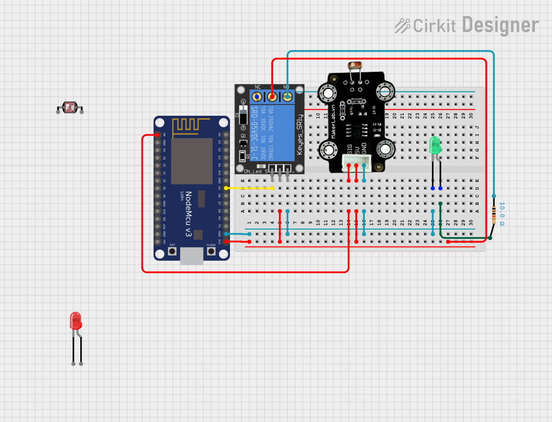
Circuit Documentation
Summary of the Circuit
This circuit is designed to utilize a NodeMCU V3 ESP8266 microcontroller to interface with various components including an LDR light sensor, LEDs, a relay, and a resistor. The NodeMCU reads the ambient light level through the LDR sensor and controls a relay based on this input. The relay can switch an external load on or off, and the LEDs indicate the status of the system. The NodeMCU is also equipped with WiFi capabilities, allowing it to connect to a network and communicate with an MQTT broker for remote monitoring and control.
Component List
NodeMCU V3 ESP8266
- Microcontroller with WiFi capability
- Pins: A0, GND, VU, S3, S2, S1, SC, S0, SK, 3V3, EN, RST, Vin, D0, D1, D2, D3, D4, D5, D6, D7, D8, RX, TX
Photocell (LDR)
- Light-dependent resistor for measuring light intensity
- Pins: pin 0, pin 1
LED: Two Pin (red)
- Red indicator LED
- Pins: cathode, anode
LED: Two Pin (green)
- Green indicator LED
- Pins: cathode, anode
1-Channel Relay (5V 10A)
- Relay module for controlling high power devices
- Pins: NC, signal, C, power, NO, ground
MKE-S02 LDR Light Sensor
- Light sensor module with digital output
- Pins: SIG, 5V, GND
Resistor
- Passive component used to limit current
- Resistance: 10 Ohms
- Pins: pin1, pin2
Wiring Details
NodeMCU V3 ESP8266
- A0: Connected to MKE-S02 LDR Light Sensor (SIG)
- 3V3: Connected to MKE-S02 LDR Light Sensor (5V), 1-Channel Relay (NC, C, NO), Resistor (pin1)
- GND: Connected to MKE-S02 LDR Light Sensor (GND), LED: Two Pin (green) (cathode)
- D5: No connection specified
Photocell (LDR)
- No connections specified
LED: Two Pin (red)
- No connections specified
LED: Two Pin (green)
- cathode: Connected to NodeMCU V3 ESP8266 (GND)
- anode: Connected to Resistor (pin2)
1-Channel Relay (5V 10A)
- NC, C, NO: Connected to NodeMCU V3 ESP8266 (3V3)
- signal, power, ground: No connections specified
MKE-S02 LDR Light Sensor
- SIG: Connected to NodeMCU V3 ESP8266 (A0)
- 5V: Connected to NodeMCU V3 ESP8266 (3V3)
- GND: Connected to NodeMCU V3 ESP8266 (GND)
Resistor
- pin1: Connected to NodeMCU V3 ESP8266 (3V3)
- pin2: Connected to LED: Two Pin (green) (anode)
Documented Code
The following code is written for the NodeMCU V3 ESP8266 microcontroller. It is designed to connect to a WiFi network, communicate with an MQTT broker, read an LDR sensor value, and control a relay based on the LDR value. It also publishes the status of the relay and LDR readings to the MQTT broker.
#include <ESP8266WiFi.h>
#include <PubSubClient.h>

// WiFi Settings
const char *ssid = "ssidwifi"; // Replace with your WiFi SSID
const char *password = "12345678"; // Replace with your WiFi password
#define LDR_PIN A0 // LDR pin initialization
#define RELAY_PIN D5 // Relay pin initialization

// MQTT Broker Settings
const char *mqtt_broker = "broker.emqx.io"; // EMQX broker endpoint
const char *mqtt_topic = "cps/topik"; // MQTT topic
const char *mqtt_username = "username"; // MQTT username for authentication
const char *mqtt_password = "password"; // MQTT password for authentication
const int mqtt_port = 1883; // MQTT port (TCP)

WiFiClient espClient; // WiFi client
PubSubClient mqtt_client(espClient); // MQTT client

// Global variables
bool ldrEnabled = true; // Flag to control LDR reading
String lastRelayStatus = ""; // Stores the last relay status
unsigned long lastPublishTime = 0; // Last publish time
const unsigned long publishInterval = 1000; // Publish interval (1 second)

// Function prototypes
void connectToWiFi();
void connectToMQTTBroker();
void mqttCallback(char *topic, byte *payload, unsigned int length);
void sendFeedback(const String &message); // Function to send feedback
void status(); // Function to send status to MQTT

void setup() {
  Serial.begin(115200); // Setup serial communication
  pinMode(RELAY_PIN, OUTPUT); // Set relay pin mode
  connectToWiFi(); // Connect to WiFi
  mqtt_client.setServer(mqtt_broker, mqtt_port); // Set MQTT server
  mqtt_client.setCallback(mqttCallback); // Set MQTT callback function
  connectToMQTTBroker(); // Connect to MQTT broker
}

// More code follows...
The code above initializes the WiFi and MQTT settings, defines pin assignments, and includes the setup function. The full code is responsible for handling WiFi and MQTT connections, processing MQTT messages to control the relay, reading the LDR sensor, and publishing status updates to the MQTT broker. It also includes error handling and reconnection logic for robust operation.