
Circuit Documentation
Summary
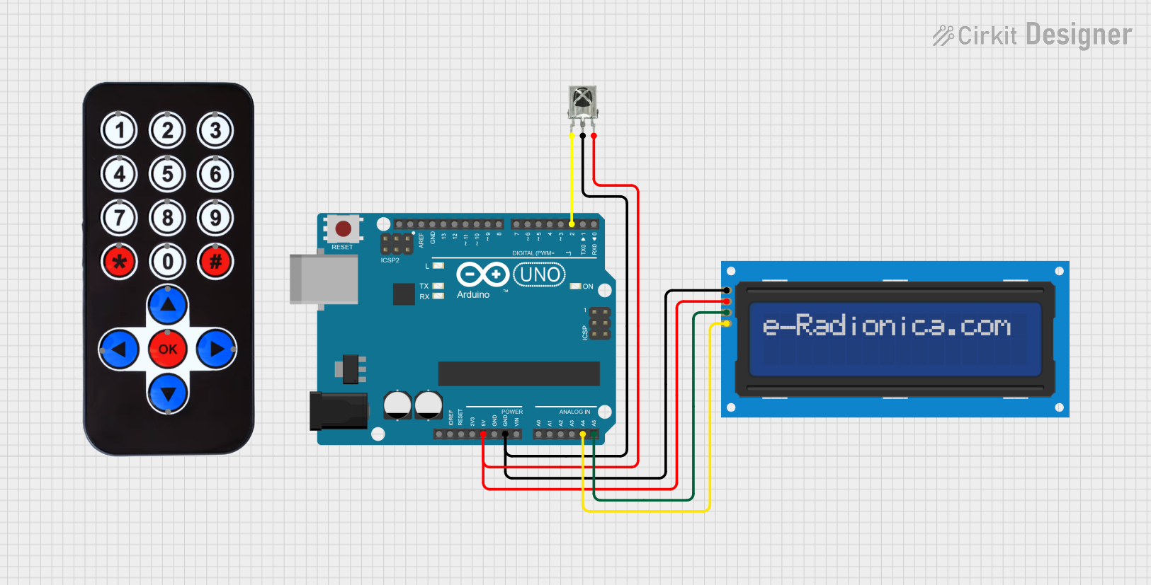
This circuit involves an Arduino UNO microcontroller interfaced with a VS1838B IR Receiver and a 16x2 I2C LCD screen. The IR receiver captures signals from an HX1838 Infrared Remote Control, and the received IR codes are displayed on the LCD screen. The Arduino UNO processes the IR signals and controls the LCD display.
Component List
Arduino UNO
- Description: A microcontroller board based on the ATmega328P.
- Pins: UNUSED, IOREF, Reset, 3.3V, 5V, GND, Vin, A0, A1, A2, A3, A4, A5, SCL, SDA, AREF, D13, D12, D11, D10, D9, D8, D7, D6, D5, D4, D3, D2, D1, D0
HX1838 Infrared IR Wireless Remote Control
- Description: An infrared remote control used to send IR signals.
- Pins: FFA25D (1), FF629D (2), FFE21D (3), FF22DD (4), FF02FD (5), FFC23D (6), FFE01F (7), FFA857 (8), FF906F (9), FF9867 (0), FFB04F (#), FF6897 (*), FF18E7 (↑), FF5AA5 (→), FF10EF (←), FF4AB5 (↓), FF38C7 (OK)
VS1838B IR Receiver
- Description: An infrared receiver module used to receive IR signals from the remote control.
- Pins: OUT, GND, VCC
LCD Screen 16x2 I2C
- Description: A 16x2 character LCD display with I2C interface.
- Pins: SCL, SDA, VCC, GND
Wiring Details
Arduino UNO
- 5V: Connected to VCC of VS1838B IR Receiver and VCC of LCD Screen 16x2 I2C
- GND: Connected to GND of VS1838B IR Receiver and GND of LCD Screen 16x2 I2C
- A4: Connected to SCL of LCD Screen 16x2 I2C
- A5: Connected to SDA of LCD Screen 16x2 I2C
- D2: Connected to OUT of VS1838B IR Receiver
VS1838B IR Receiver
- VCC: Connected to 5V of Arduino UNO
- GND: Connected to GND of Arduino UNO
- OUT: Connected to D2 of Arduino UNO
LCD Screen 16x2 I2C
- VCC: Connected to 5V of Arduino UNO
- GND: Connected to GND of Arduino UNO
- SCL: Connected to A4 of Arduino UNO
- SDA: Connected to A5 of Arduino UNO
Code Documentation
Code Overview
The provided code initializes the IR receiver and the LCD screen. It reads IR signals from the remote control and displays the received IR codes on the LCD screen.
Code
#include <IRremote.h>
#include <Wire.h>
#include <LiquidCrystal_I2C.h>

const int RECV_PIN = 2; // Pin connected to the IR receiver OUT pin (D2)
IRrecv irrecv(RECV_PIN);
decode_results results;

// Set the LCD address to 0x27 for a 16 chars and 2 line display
LiquidCrystal_I2C lcd(0x27, 16, 2);

void setup() {
  Serial.begin(9600); // Initialize serial communication
  irrecv.enableIRIn(); // Start the IR receiver

  // Initialize the LCD
  lcd.init();
  lcd.backlight();
  lcd.setCursor(0, 0);
  lcd.print("IR Code: ");
}

void loop() {
  if (irrecv.decode()) {
    unsigned long irCode = irrecv.decodedIRData.decodedRawData;
    Serial.print("IR Code: ");
    Serial.println(irCode, HEX); // Print the received IR code in HEX

    // Display the IR code on the LCD
    lcd.setCursor(0, 1);
    lcd.print("                "); // Clear the previous code
    lcd.setCursor(0, 1);
    lcd.print(irCode, HEX);

    irrecv.resume(); // Receive the next value
  }
}
Code Explanation
- Libraries: The code includes the
IRremotelibrary for IR signal processing and theLiquidCrystal_I2Clibrary for controlling the LCD screen. - Pin Configuration: The IR receiver is connected to digital pin 2 (D2) of the Arduino.
- LCD Initialization: The LCD is initialized with the I2C address
0x27and set to display 16 characters on 2 lines. - Setup Function: Initializes serial communication, starts the IR receiver, and sets up the LCD display.
- Loop Function: Continuously checks for received IR signals. When a signal is received, it prints the IR code to the serial monitor and displays it on the LCD screen. The previous code on the LCD is cleared before displaying the new code.