Arduino 101 BLDC Motor Controller with LCD Display and Potentiometer
Circuit Documentation
Summary
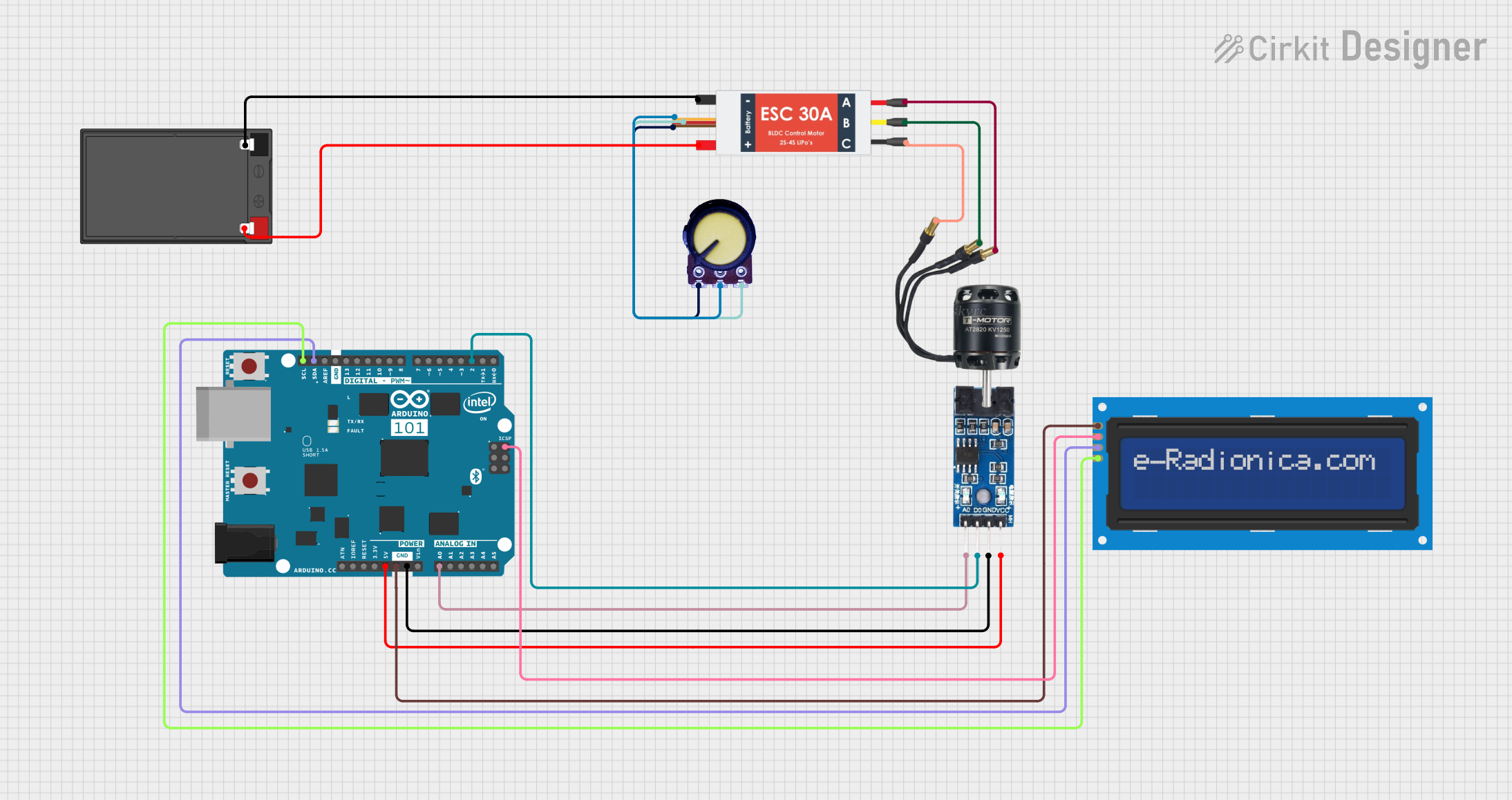
This document provides a detailed overview of a circuit that includes an Arduino 101 microcontroller, an LM393 comparator, a BLDC motor controlled by an Electronic Speed Controller (ESC), a potentiometer, a battery, and an LCD screen. The circuit is designed to control the speed of the BLDC motor using the potentiometer and display relevant information on the LCD screen.
Component List
LM393 Comparator
- Pins: VCC, GND, D0, A0
- Description: A dual comparator used for comparing voltage levels.
- Purpose in Circuit: Used to compare voltage levels and provide digital output to the Arduino.
BLDC Motor
- Pins: Wire A, Wire B, Wire C
- Description: A brushless DC motor.
- Purpose in Circuit: Provides mechanical motion controlled by the ESC.
Electronic Speed Controller (ESC)
- Pins: Battery VCC, Battery GND, Signal, 5v out, GND out, M1, M2, M3
- Description: Controls the speed of the BLDC motor.
- Purpose in Circuit: Receives control signals from the potentiometer and powers the BLDC motor.
Potentiometer
- Pins: GND, Output, VCC
- Description: A variable resistor.
- Purpose in Circuit: Provides an adjustable voltage signal to control the ESC.
Battery
- Pins: +, -
- Description: Power source for the circuit.
- Purpose in Circuit: Supplies power to the ESC and other components.
Arduino 101
- Pins: A5/SCL, A4/SDA, AREF, GND, D13/SCK, D12/MISO, D11 PWM/MOSI, D10 PWM/SS, D9 PWM, D8, D7, D6 PWM, D5 PWM, D4, D3 PWM, D2, D1/TX, D0/RX, AIN, ioref, RESET, 3V3, 5V, VIN, A0, A1, A2, A3, ICSP MISO, ICSP SCK, ICSP MOSI
- Description: A microcontroller board based on the Intel Curie module.
- Purpose in Circuit: Acts as the main controller for the circuit, processing inputs and controlling outputs.
LCD Screen 16x2 I2C
- Pins: SCL, SDA, VCC, GND
- Description: A 16x2 character LCD with I2C interface.
- Purpose in Circuit: Displays information such as motor speed and other data.
Wiring Details
LM393 Comparator
- VCC connected to Arduino 101 5V
- GND connected to Arduino 101 GND
- D0 connected to Arduino 101 D2
- A0 connected to Arduino 101 A0
BLDC Motor
- Wire A connected to ESC M3
- Wire B connected to ESC M2
- Wire C connected to ESC M1
Electronic Speed Controller (ESC)
- Battery VCC connected to Battery +
- Battery GND connected to Battery -
- Signal connected to Potentiometer Output
- 5v out connected to Potentiometer VCC
- GND out connected to Potentiometer GND
Potentiometer
- GND connected to ESC GND out
- Output connected to ESC Signal
- VCC connected to ESC 5v out
Battery
- + connected to ESC Battery VCC
- - connected to ESC Battery GND
Arduino 101
- 5V connected to LM393 VCC
- GND connected to LM393 GND
- D2 connected to LM393 D0
- A0 connected to LM393 A0
- A5/SCL connected to LCD Screen SCL
- A4/SDA connected to LCD Screen SDA
- GND connected to LCD Screen GND
- 5V connected to LCD Screen VCC
LCD Screen 16x2 I2C
- SCL connected to Arduino 101 A5/SCL
- SDA connected to Arduino 101 A4/SDA
- GND connected to Arduino 101 GND
- VCC connected to Arduino 101 5V
Code
No code is provided for this circuit.
This document provides a comprehensive overview of the circuit, including a summary, component list, wiring details, and code section. Each component is described, and its connections are detailed to ensure proper assembly and functionality.