
Arduino 101 and ESP32 CAM Motion-Activated Servo Control System
View and Edit Project In Cirkit Designer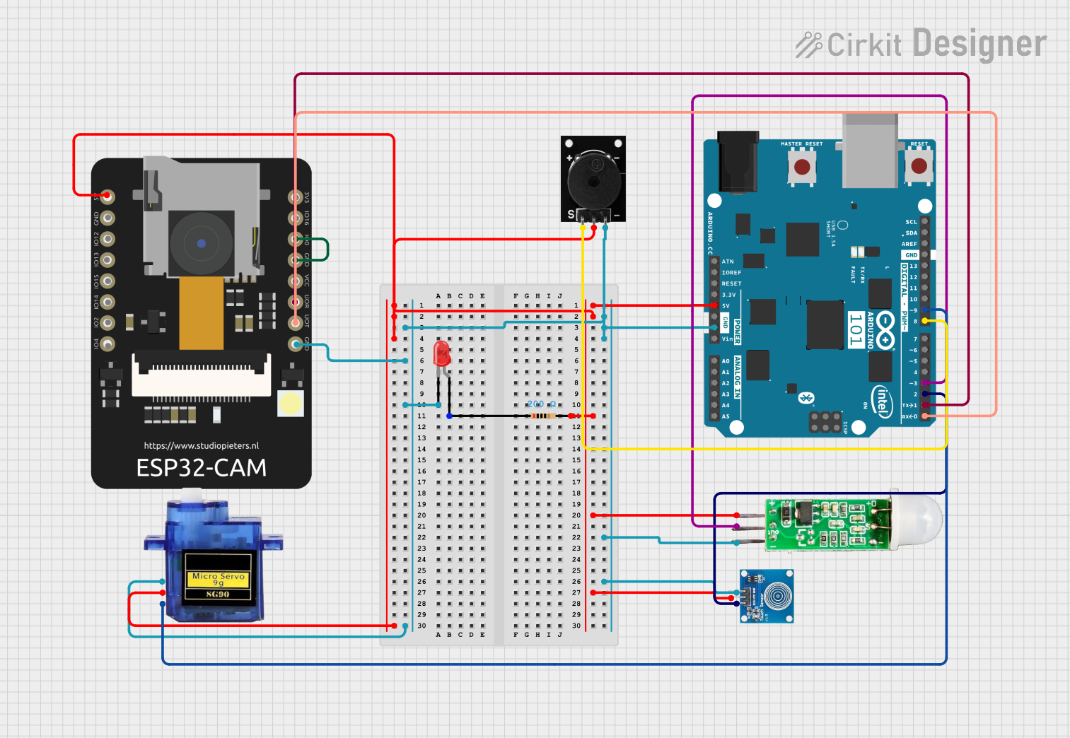
Circuit Documentation
Summary
This circuit integrates various components including an Arduino 101, a touch sensor, a PIR motion sensor (HC-SR505), an ESP32 CAM module, a passive buzzer, a red LED, a micro servo 9G, and a resistor. The Arduino 101 serves as the central processing unit, interfacing with the sensors, actuator, and communication module to perform specific tasks based on the input from the touch sensor and PIR motion sensor. The ESP32 CAM module enables image capture and potential wireless communication. The passive buzzer and LED provide audio and visual feedback, respectively, while the micro servo 9G is an actuator controlled by the Arduino. The resistor is used to limit current to the LED.
Component List
Arduino 101
- Microcontroller board based on the Intel Curie module
- Features digital I/O pins, analog input pins, PWM pins, and communication interfaces
Touch Sensor
- Capacitive touch sensor module
- Used to detect touch or proximity
HC-SR505 Mini PIR Motion Sensing Module
- Compact passive infrared sensor module
- Detects motion through changes in infrared levels emitted by objects
ESP32 CAM
- Wi-Fi and Bluetooth enabled camera module
- Features multiple GPIOs and supports image capture
Passive Buzzer
- Electromagnetic buzzer that emits sound when powered
- Used for audio signaling
LED: Two Pin (red)
- Basic red LED for visual indication
- Requires current-limiting resistor to prevent damage
Micro servo 9G
- Small and lightweight servo motor
- Used for precise angular movement
Resistor (200 Ohms)
- Limits current to prevent damage to components such as LEDs
Wiring Details
Arduino 101
D9 PWMconnected to Micro servo 9G (PWM signal)D8connected to Passive Buzzer (signal)D3 PWMconnected to HC-SR505 Mini PIR Motion Sensing Module (output signal)D2connected to Touch Sensor (IO signal)D1/TXconnected to ESP32 CAM (RX)D0/RXconnected to ESP32 CAM (TX)5Vconnected to 5V power rail supplying Touch Sensor, HC-SR505, ESP32 CAM, Passive Buzzer, and Micro servo 9GGNDconnected to ground rail supplying all components
Touch Sensor
IOconnected to Arduino 101 (D2)VCCconnected to 5V power railGNDconnected to ground rail
HC-SR505 Mini PIR Motion Sensing Module
+connected to 5V power railoutconnected to Arduino 101 (D3 PWM)-connected to ground rail
ESP32 CAM
5Vconnected to 5V power railGNDconnected to ground railGPIO3 / RXconnected to Arduino 101 (D1/TX)GPIO1 / TXconnected to Arduino 101 (D0/RX)GPIO0connected to ground rail (for programming mode)
Passive Buzzer
S output signalconnected to Arduino 101 (D8)+VCCconnected to 5V power railGNDconnected to ground rail
LED: Two Pin (red)
anodeconnected to one end of the resistor (200 Ohms)cathodeconnected to ground rail
Micro servo 9G
PWMconnected to Arduino 101 (D9 PWM)+5Vconnected to 5V power railGNDconnected to ground rail
Resistor (200 Ohms)
- One end connected to LED anode
- Other end connected to 5V power rail
Documented Code
No code has been provided for the microcontrollers in the circuit. The documentation of the code would typically include descriptions of the functions, initialization procedures, main loop, and any interrupt service routines. Since there is no code to document, this section remains empty until code is provided.