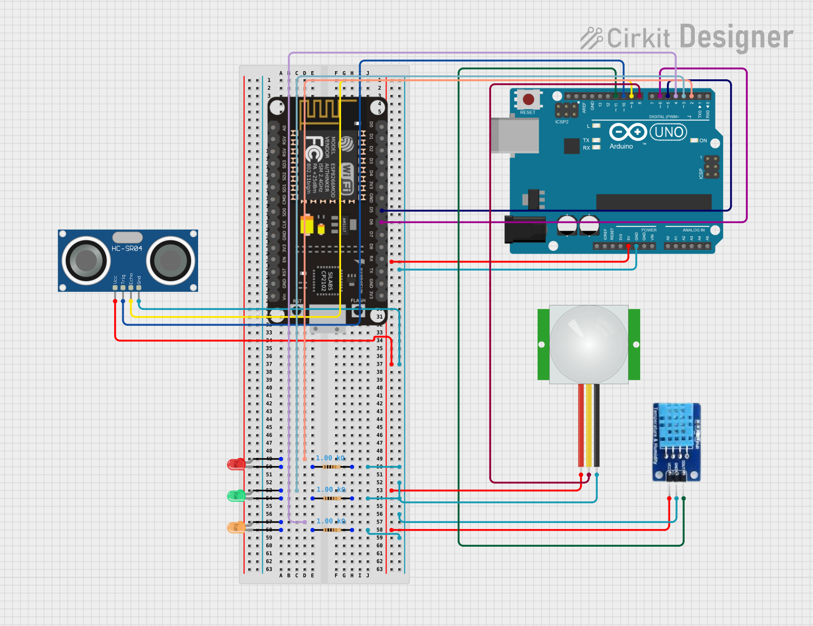
Arduino UNO and ESP-8266 Based Sensor Monitoring System with Visual Indicators

Circuit Documentation
Summary
This document provides a detailed overview of a circuit designed to interface an ESP-8266 controller and an Arduino UNO with various sensors and LEDs. The circuit includes an ultrasonic sensor (HC-SR04), a PIR motion sensor, a DHT11 temperature and humidity sensor, and three LEDs (red, orange, and green) each with a corresponding resistor. The Arduino UNO serves as the central processing unit, controlling the sensors and LEDs, while the ESP-8266 controller is used for potential WiFi capabilities. The circuit is powered by the Arduino UNO's 5V output, and ground connections are shared among components.
Component List
- ESP-8266 Controller: A WiFi-capable microcontroller with a variety of digital pins.
- Arduino UNO: A microcontroller board based on the ATmega328P, with digital and analog I/O pins.
- HC-SR04 Ultrasonic Sensor: A sensor for measuring distance via ultrasonic sound waves.
- PIR Sensor: A motion sensor that detects changes in infrared radiation.
- DHT11: A sensor for measuring temperature and humidity.
- LED (Red): A red light-emitting diode.
- LED (Orange): An orange light-emitting diode.
- LED (Green): A green light-emitting diode.
- Resistor (1k Ohms): Three resistors with a resistance of 1000 Ohms each, used to limit current to the LEDs.
Wiring Details
ESP-8266 Controller
- D5 connected to Arduino UNO's D5.
- D6 connected to Arduino UNO's D6.
Arduino UNO
- D2 connected to the anode of the red LED.
- D3 connected to the anode of the green LED.
- D4 connected to the anode of the orange LED.
- D5 connected to ESP-8266's D5.
- D6 connected to ESP-8266's D6.
- D8 connected to the signal pin of the PIR sensor.
- D9 connected to the ECHO pin of the HC-SR04 Ultrasonic Sensor.
- D10 connected to the TRIG pin of the HC-SR04 Ultrasonic Sensor.
- D11 connected to the DATA pin of the DHT11 sensor.
- 5V connected to VCC pins of HC-SR04 Ultrasonic Sensor, PIR sensor, and DHT11.
- GND connected to ground pins of all components.
HC-SR04 Ultrasonic Sensor
- VCC connected to Arduino UNO's 5V.
- TRIG connected to Arduino UNO's D10.
- ECHO connected to Arduino UNO's D9.
- GND connected to common ground.
PIR Sensor
- VDD connected to Arduino UNO's 5V.
- SIG connected to Arduino UNO's D8.
- GND connected to common ground.
DHT11
- VCC connected to Arduino UNO's 5V.
- DATA connected to Arduino UNO's D11.
- GND connected to common ground.
LED (Red)
- Anode connected to Arduino UNO's D2.
- Cathode connected to a 1k Ohm resistor.
LED (Orange)
- Anode connected to Arduino UNO's D4.
- Cathode connected to a 1k Ohm resistor.
LED (Green)
- Anode connected to Arduino UNO's D3.
- Cathode connected to a 1k Ohm resistor.
Resistor (1k Ohms)
- Three resistors each connected between the cathode of an LED and common ground.
Documented Code
Arduino UNO Code (sketch.ino)
void setup() {
  // put your setup code here, to run once:

}

void loop() {
  // put your main code here, to run repeatedly:

}
Note: The provided code is a template and does not include specific functionality. It should be populated with the logic required to control the sensors and LEDs based on the design requirements.