Cirkit Designer
Your all-in-one circuit design IDE
Home /
Project Documentation
Wi-Fi Controlled AC Dimmer with Wemos D1 Mini
Circuit Documentation
Summary
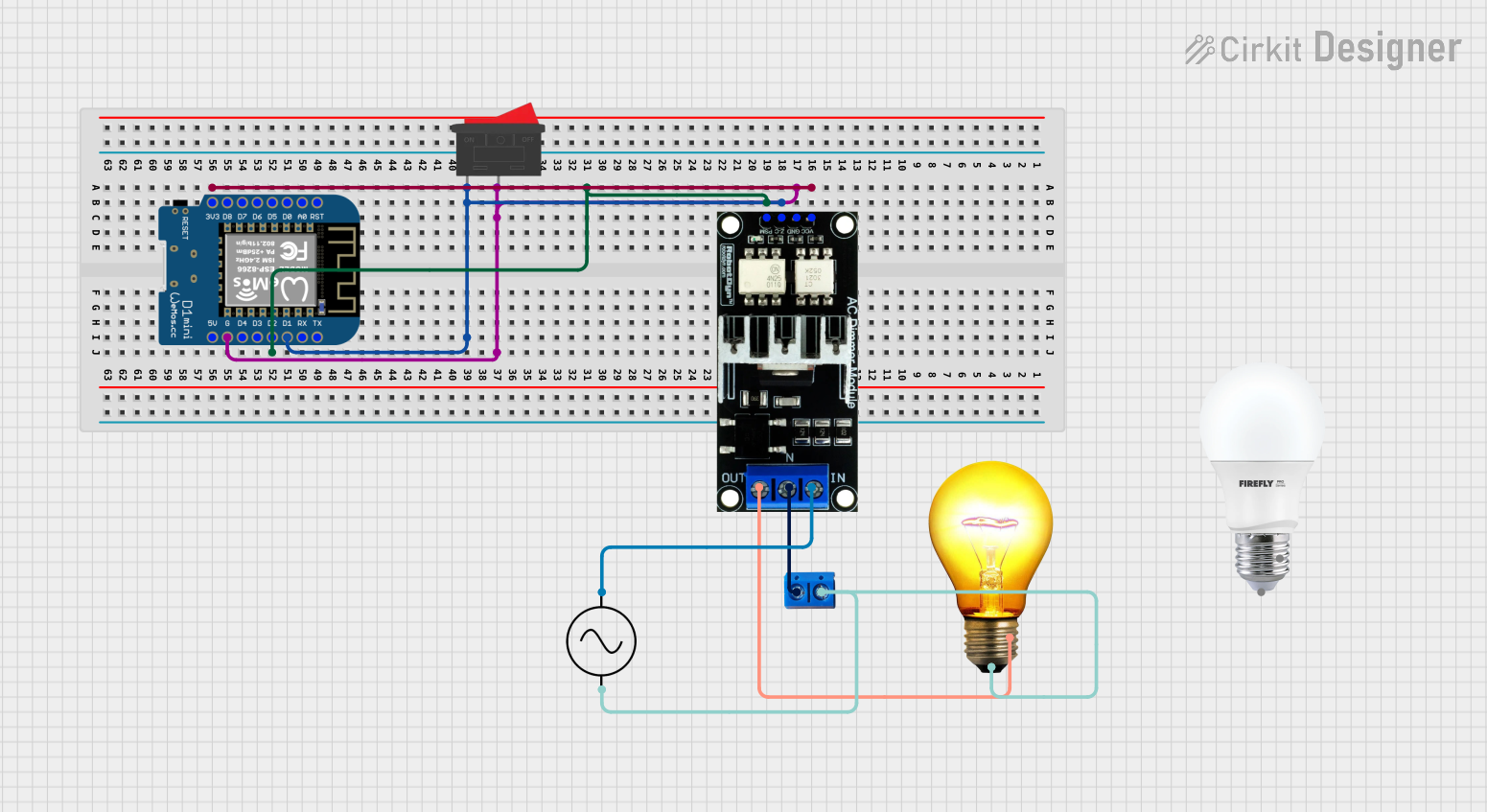
This circuit is designed to control the brightness of an AC bulb using a Wemos D1 Mini microcontroller and an AC Dimmer Lamp Module. The system is powered by an AC supply and includes a rocker switch for user interaction. The microcontroller adjusts the brightness of the bulb by sending PWM signals to the dimmer module based on the input from the rocker switch.
Component List
Wemos D1 Mini
- Microcontroller board based on the ESP8266.
- Pins: RST, A0, D0, D5, D6, D7, D8, 3V3, 5V, G, D4, D3, D2, D1, RX, TX.
Rocker Switch
- A simple on/off switch with two terminals.
- Pins: 1, 2.
AC Supply
- Provides the main power source for the circuit.
- Pins: +ve, -ve.
AC Dimmer Lamp Module
- Controls the power delivered to an AC load using PWM signals.
- Pins: VCC, GND, Z-C, PWM, N, L.
AC Bulb
- The load in the circuit, which is an AC-powered light bulb.
- Pins: P, N.
Terminal PCB 2 Pin
- A connector for interfacing external components with the circuit.
- Pins: Pin A, Pin B.
Wiring Details
Wemos D1 Mini
- 3V3 connected to VCC of AC Dimmer Lamp Module.
- G connected to GND of AC Dimmer Lamp Module and pin 2 of Rocker Switch.
- D1 connected to Z-C of AC Dimmer Lamp Module and pin 1 of Rocker Switch.
- D2 connected to PWM of AC Dimmer Lamp Module.
Rocker Switch
- Pin 1 connected to Z-C of AC Dimmer Lamp Module and D1 of Wemos D1 Mini.
- Pin 2 connected to GND of AC Dimmer Lamp Module and G of Wemos D1 Mini.
AC Supply
- +ve connected to L of AC Dimmer Lamp Module.
- -ve connected to P of AC Bulb and Pin B of Terminal PCB 2 Pin.
AC Dimmer Lamp Module
- VCC connected to 3V3 of Wemos D1 Mini.
- GND connected to G of Wemos D1 Mini and pin 2 of Rocker Switch.
- Z-C connected to D1 of Wemos D1 Mini and pin 1 of Rocker Switch.
- PWM connected to D2 of Wemos D1 Mini.
- N connected to Pin A of Terminal PCB 2 Pin.
- L connected to +ve of AC Supply.
AC Bulb
- N connected to GND of AC Dimmer Lamp Module.
- P connected to Pin B of Terminal PCB 2 Pin and -ve of AC Supply.
Terminal PCB 2 Pin
- Pin A connected to N of AC Dimmer Lamp Module.
- Pin B connected to P of AC Bulb and -ve of AC Supply.
Documented Code
#define LED_PIN 4  // D2 on Wemos D1 Mini
#define SW1_PIN 5  // D1 on Wemos D1 Mini

int brightness = 0; // Initial brightness (0-255)

void setup() {
  pinMode(LED_PIN, OUTPUT);
  pinMode(SW1_PIN, INPUT_PULLUP);
}

void loop() {
  int buttonState = digitalRead(SW1_PIN);

  if (buttonState == HIGH) {
    if (brightness < 255) {
      brightness++;
      analogWrite(LED_PIN, brightness);
      delay(3);
    }
  } else if (buttonState == LOW) {
    if (brightness > 0) {
      brightness--;
      analogWrite(LED_PIN, brightness);
      delay(2);
    }
  }
}
Note: The LED_PIN is defined as pin 4 (D2 on Wemos D1 Mini) and SW1_PIN as pin 5 (D1 on Wemos D1 Mini). The code is designed to increase or decrease the brightness of the AC bulb by adjusting the PWM signal sent to the AC Dimmer Lamp Module. The brightness level is modified based on the state of the rocker switch.