
ESP32C3 Supermini Based Interactive Reaction Game with RGB LED Effects and ESP-NOW Communication
View and Edit Project In Cirkit Designer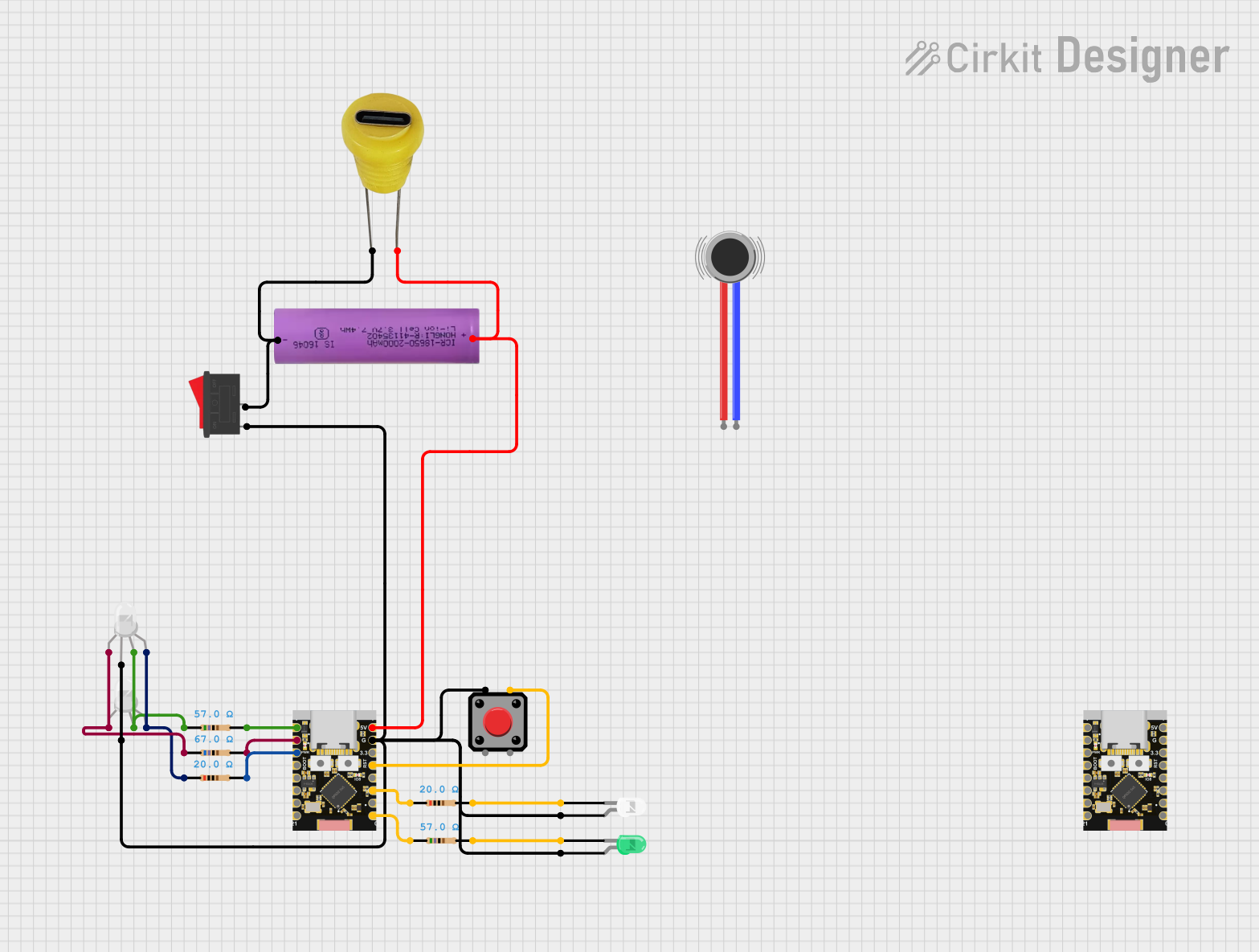
Circuit Documentation
Summary
This circuit incorporates multiple components including two ESP32C3 Supermini microcontrollers, various resistors, pushbuttons, RGB LEDs, a Li-ion battery, a rocker switch, green and white LEDs, and a 5V Type C DC socket. The circuit is designed to facilitate a reaction time game, where players press a button in response to an LED signal. The ESP32C3 microcontrollers communicate with each other using ESP-NOW protocol to synchronize game states and determine the winner based on reaction times.
Component List
Microcontrollers
- ESP32C3 Supermini: A compact module with Wi-Fi capabilities, multiple GPIOs, and support for ESP-NOW communication.
Resistors
- 57 Ohm Resistor: Limits current to protect connected components.
- 67 Ohm Resistor: Provides current limiting for LEDs or other components.
- 20 Ohm Resistor: Used for current limiting in low-resistance applications.
Input Devices
- Pushbutton: A momentary switch used to trigger events in the circuit.
Output Devices
- RGB LED (Wokwi compatible): A multi-color LED capable of displaying various colors.
- LED: Two Pin (green): A single-color LED that emits green light.
- LED: Two Pin (white): A single-color LED that emits white light.
Power Components
- Li-ion battery 18650-2000mAh 3.7V 7.4WH: Provides power to the circuit.
- Rocker Switch: Acts as an on/off switch for the circuit.
- 5V Type C DC Socket: Allows the circuit to be powered via a USB Type C connection.
Actuators
- Vibration Motor: Provides haptic feedback.
Wiring Details
ESP32C3 Supermini
- GPIO05: Connected to a 57 Ohm resistor.
- GPIO06: Connected to a 67 Ohm resistor.
- GPIO07: Connected to a 20 Ohm resistor.
- GPIO00: Connected to a 57 Ohm resistor.
- GPIO02: Connected to a 20 Ohm resistor.
- GPIO04: Connected to a pushbutton.
- GND: Common ground for pushbutton, RGB LEDs, rocker switch, green and white LEDs.
- +5V: Connected to the positive terminal of the Li-ion battery and the 5V Type C DC socket.
Resistors
- 57 Ohm Resistor: One end connected to ESP32C3 Supermini GPIO05, the other end to the green pin of RGB LEDs.
- 67 Ohm Resistor: One end connected to ESP32C3 Supermini GPIO06, the other end to the red pin of RGB LEDs.
- 20 Ohm Resistor: One end connected to ESP32C3 Supermini GPIO07, the other end to the blue pin of RGB LEDs.
Pushbutton
- Pin 4: Connected to ESP32C3 Supermini GPIO04.
- Pin 1: Connected to the common ground net.
RGB LED (Wokwi compatible)
- COM: Connected to the common ground net.
- G: Connected to a 57 Ohm resistor.
- R: Connected to a 67 Ohm resistor.
- B: Connected to a 20 Ohm resistor.
Li-ion battery 18650-2000mAh 3.7V 7.4WH
- +: Connected to the +5V net.
- -: Connected to the common ground net.
Rocker Switch
- Pin 1: Connected to the common ground net.
- Pin 2: Connected to the negative terminal of the Li-ion battery and the negative pin of the 5V Type C DC socket.
LED: Two Pin (green)
- Anode: Connected to the common ground net.
- Cathode: Connected to a 57 Ohm resistor.
LED: Two Pin (white)
- Anode: Connected to the common ground net.
- Cathode: Connected to a 20 Ohm resistor.
5V Type C DC Socket
- + Positive: Connected to the +5V net.
- - Negative: Connected to the common ground net.
Documented Code
ESP32C3 Supermini (Master)
#include <esp_now.h>
#include <WiFi.h>
#include <iostream>

// Define pin assignments
#define READY_LED_PIN 0
#define REACTION_LED_PIN 2
#define GREEN_LED_PIN 5
#define RED_LED_PIN 6
#define BLUE_LED_PIN 7
#define BUTTON_PIN 4

// Define timing constants
#define LONG_PRESS_DURATION 5000
#define SHORT_PRESS_DURATION 2000
#define MIN_DELAY 5000
#define MAX_DELAY 30000
#define NUMBER_MODES 5

// Define client address for ESP-NOW communication
uint8_t clientAddress[] = {0xD8, 0x3B, 0xDA, 0xE6, 0x91, 0x6C};

// Game state variables
bool masterReady = false;
bool clientReady = false;
bool gameActive = false;
bool gameStarted = false;
unsigned long buttonPressTime;
unsigned long reactionStartTime;
unsigned long masterReactionTime = 0;
unsigned long clientReactionTime = 0;

// LED flickering effect variables
unsigned long prevMillis = 0;
unsigned long flickerInterval = 100;

// Button state variables
bool buttonWasHeld = false;
int currentMode = 0;

// RGB LED color transition variables
const unsigned long interval = 50;
int redValue = 255;
int greenValue = 0;
int blueValue = 0;
int step = 5;

// Reaction LED state variables
bool reactionLedState = false;
bool buttonWasPressed = false;

// ESP-NOW message structure
typedef struct {
  char message[16];
  unsigned long reactionTime;
} esp_now_message;

// Function prototypes (to be implemented in the code)
void setup();
void loop();
void resetRGBLED();
void Fireworks();
void LGBTQ();
void controlFlameEffect(int pin_number);
void checkButton();
void startGame();
void playGame();
void onDataReceive(const esp_now_recv_info *info, const uint8_t *incomingData, int len);
void evaluateWinner();
void displayWinner();
void resetGame();
void sendMessage(const char *messageText);
void controlReactionLed();

// ... (rest of the code)
ESP32C3 Supermini (Client)
#include <esp_now.h>
#include <WiFi.h>

// Define pin assignments
#define LED_PIN 0
#define REACTION_LED_PIN 2
#define BUTTON_PIN 4

// Define timing constants
#define LONG_PRESS_DURATION 5000

// Define master address for ESP-NOW communication
uint8_t masterAddress[] = {0xD8, 0x3B, 0xDA, 0xE6, 0xB7, 0x50};

// Game state variables
bool clientReady = false;
bool gameActive = false;
bool gameStarted = false;
unsigned long buttonPressTime;
unsigned long reactionStartTime;
unsigned long clientReactionTime = 0;

// Reaction LED state variables
bool reactionLedState = false;
bool buttonWasPressed = false;

// ESP-NOW message structure
typedef struct {
  char message[16];
  unsigned long reactionTime;
} esp_now_message;

// Function prototypes (to be implemented in the code)
void setup();
void loop();
void checkButton();
void onDataReceive(const esp_now_recv_info *info, const uint8_t *incomingData, int len);
void playGame();
void displayWinner();
void resetGame();
void sendMessage(const char *messageText);
void sendReactionTime();
void controlReactionLed();

// ... (rest of the code)
This documentation provides an overview of the circuit, including a summary, detailed component list, wiring instructions, and documented code for the microcontrollers. The code snippets are partial and represent the structure and key elements of the embedded software.