
Arduino UNO R4 WiFi and RS485 to TTL Interface Circuit with Pushbutton and LED Indicators
View and Edit Project In Cirkit Designer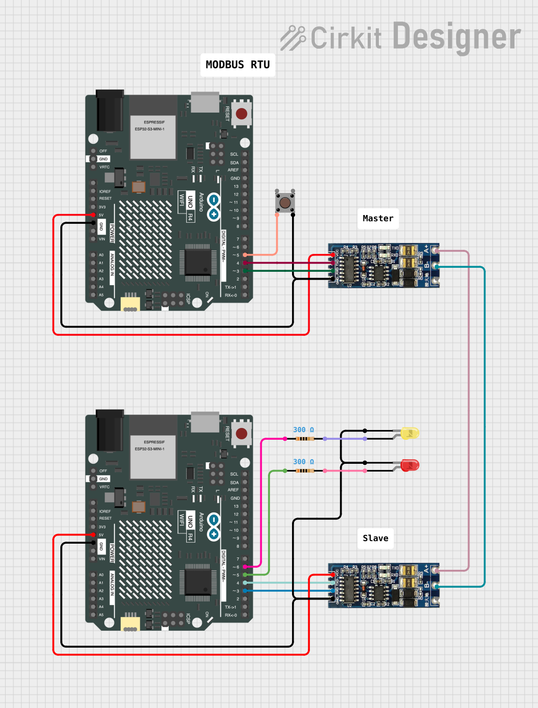
Circuit Documentation
Summary
The circuit in question appears to be designed to interface an Arduino UNO R4 WiFi with an RS485 to TTL (UART) converter module. The purpose of this setup is likely to enable the Arduino to communicate over an RS485 network, which is commonly used for industrial control systems due to its robustness and long-distance capabilities.
The circuit also includes pushbuttons and LEDs (one yellow and one red), which are typically used for user input and status indication, respectively. The LEDs are connected through resistors to limit the current and protect the LEDs from damage.
Component List
Arduino UNO R4 WiFi
- Microcontroller board based on the ATmega328
- Features digital I/O pins, analog input pins, and various power pins
- Equipped with WiFi capabilities for wireless communication
RS485 to TTL (UART) Converter
- Module that converts between RS485 signals and TTL-compatible signals
- Allows microcontrollers to communicate over an RS485 network
Pushbutton
- A simple switch mechanism for control of a machine or process
- Typically used as an input device to trigger an event
Resistor (300 Ohms)
- Passive two-terminal electrical component that implements electrical resistance
- Used to limit current or divide voltages in a circuit
LED: Two Pin (yellow)
- A yellow light-emitting diode
- Used as an indicator light
LED: Two Pin (red)
- A red light-emitting diode
- Used as an indicator light
Wiring Details
Arduino UNO R4 WiFi
5Vpin provides power to the RS485 to TTL (UART) converter moduleGNDpin is connected to the ground pins of the pushbutton, RS485 to TTL (UART) converter module, and LEDsD3pin is connected to the RXD pin of the RS485 to TTL (UART) converter moduleD4pin is connected to the TXD pin of the RS485 to TTL (UART) converter moduleD5pin is connected to one side of the pushbutton and through a 300 Ohm resistor to the anode of the red LEDD6pin is connected through a 300 Ohm resistor to the anode of the yellow LED
RS485 to TTL (UART) Converter
VCCpin connected to the 5V output from the ArduinoGNDpin connected to the groundRXDpin connected to the D3 pin of the ArduinoTXDpin connected to the D4 pin of the ArduinoB-andA+pins are used for RS485 communication and are interconnected between two RS485 to TTL (UART) converter modules
Pushbutton
- One side connected to the ground (GND)
- The other side connected to the D5 pin of the Arduino
Resistor (300 Ohms)
- One resistor is connected between the D5 pin of the Arduino and the anode of the red LED
- Another resistor is connected between the D6 pin of the Arduino and the anode of the yellow LED
LED: Two Pin (yellow)
- Cathode connected to the ground (GND)
- Anode connected through a 300 Ohm resistor to the D6 pin of the Arduino
LED: Two Pin (red)
- Cathode connected to the ground (GND)
- Anode connected through a 300 Ohm resistor to the D5 pin of the Arduino
Documented Code
No code was provided for the microcontrollers in the circuit. Typically, the code would be used to control the behavior of the microcontroller, such as reading the state of the pushbutton, controlling the LEDs, and managing the RS485 communication. Without the code, we cannot document the specific functionalities implemented in the circuit.