Cirkit Designer
Your all-in-one circuit design IDE
Home /
Project Documentation
Arduino-Based Fall Detection and Heart Rate Monitoring System with MPU-6050 and Pulse Sensor

Circuit Documentation
Summary
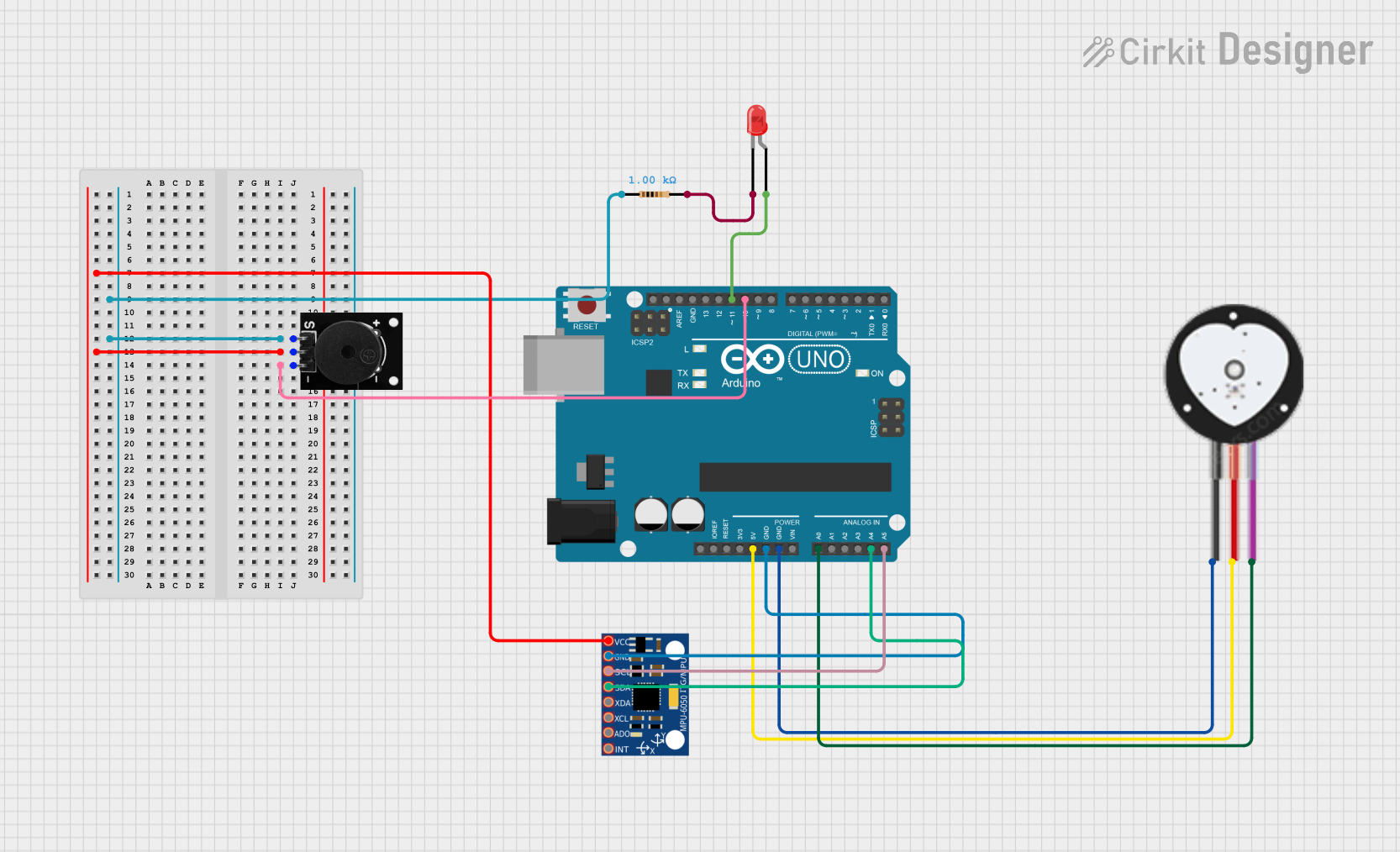
This circuit is designed to monitor heart rate and detect falls using an MPU-6050 accelerometer, a heart pulse sensor, and an Arduino UNO. The circuit also includes a passive buzzer and an LED to provide alerts based on the sensor readings.
Component List
Heart Pulse Sensor
- Pins: GND, VCC, SIGNAL
- Description: Measures the heart rate.
- Purpose in Circuit: Provides heart rate data to the Arduino.
Resistor
- Pins: pin1, pin2
- Description: 1000 Ohms resistor.
- Purpose in Circuit: Limits current to the LED.
Arduino UNO
- Pins: UNUSED, IOREF, Reset, 3.3V, 5V, GND, Vin, A0, A1, A2, A3, A4, A5, SCL, SDA, AREF, D13, D12, D11, D10, D9, D8, D7, D6, D5, D4, D3, D2, D1, D0
- Description: Microcontroller board.
- Purpose in Circuit: Central processing unit for the circuit, reads sensor data and controls the buzzer and LED.
LED: Two Pin (red)
- Pins: cathode, anode
- Description: Red LED.
- Purpose in Circuit: Provides visual alerts.
MPU-6050
- Pins: VCC, GND, SCL, SDA, XDA, XCL, AD0, INT
- Description: Accelerometer and gyroscope sensor.
- Purpose in Circuit: Detects falls by measuring acceleration.
Passive Buzzer
- Pins: S output signal, +VCC, GND
- Description: Emits sound when activated.
- Purpose in Circuit: Provides audible alerts.
Wiring Details
Heart Pulse Sensor
- GND connected to Arduino UNO GND
- VCC connected to Arduino UNO 5V
- SIGNAL connected to Arduino UNO A0
Resistor
- pin1 connected to Passive Buzzer S output signal
- pin2 connected to LED: Two Pin (red) cathode
Arduino UNO
- 5V connected to Heart Pulse Sensor VCC
- GND connected to MPU-6050 GND
- GND connected to Heart Pulse Sensor GND
- A0 connected to Heart Pulse Sensor SIGNAL
- A4 connected to MPU-6050 SDA
- A5 connected to MPU-6050 SCL
- D10 connected to Passive Buzzer GND
- D11 connected to LED: Two Pin (red) anode
LED: Two Pin (red)
- anode connected to Arduino UNO D11
- cathode connected to Resistor pin2
MPU-6050
- VCC connected to Passive Buzzer +VCC
- GND connected to Arduino UNO GND
- SDA connected to Arduino UNO A4
- SCL connected to Arduino UNO A5
Passive Buzzer
- S output signal connected to Resistor pin1
- +VCC connected to MPU-6050 VCC
- GND connected to Arduino UNO D10
Code Documentation
Arduino UNO Code
#include <Wire.h>
#include <MPU6050.h>

MPU6050 mpu;

const float FALL_THRESHOLD = 2.5;     // 낙상 감지를 위한 가속도 임계값
const int buzzerPin = 10;             // 부저 핀
const int ledPin = 9;                 // LED 핀
const int heartSensorPin = A0;        // 심박 센서 핀
const int volume = 1;                 // 부저 볼륨(PWM 값)
const int heartRateThreshold = 60;    // 심박수 임계값 (예시: 60 BPM)
unsigned long lastFallTime = 0;       // 마지막 낙상 감지 시간
const unsigned long debounceTime = 2000; // 낙상 감지 후 2초 동안 새로운 감지 방지

void setup() {
  Serial.begin(9600);
  Wire.begin();
  mpu.initialize();

  pinMode(buzzerPin, OUTPUT);
  pinMode(ledPin, OUTPUT);
  pinMode(heartSensorPin, INPUT);

  if (!mpu.testConnection()) {
    Serial.println("MPU6050 연결 실패");
    while (1);
  }
}

void loop() {
  // 센서 데이터 읽기
  int16_t ax, ay, az;
  mpu.getAcceleration(&ax, &ay, &az);

  // 가속도를 m/s²로 변환 (1g ≈ 9.81m/s²)
  float accelX = ax / 16384.0 * 9.81;
  float accelY = ay / 16384.0 * 9.81;
  float accelZ = az / 16384.0 * 9.81;

  // 현재 시간
  unsigned long currentTime = millis();

  // 낙상 감지
  if (accelZ < FALL_THRESHOLD && (accelX > 1 || accelY > 1)) {
    if (currentTime - lastFallTime > debounceTime) { // debounce time 체크
      Serial.println("낙상 감지!");

      // LED 켜기
      digitalWrite(ledPin, HIGH);
      delay(500);                   // 0.5초 동안 LED 켜기
      digitalWrite(ledPin, LOW);    // LED 끄기

      // 부저 낮은 소리로 켜기
      analogWrite(buzzerPin, volume);
      delay(1000);                  // 1초 동안 부저 울리기
      analogWrite(buzzerPin, 0);    // 부저 끄기

      lastFallTime = currentTime;   // 마지막 낙상 감지 시간 갱신
    }
  }

  // 심박수 측정
  int heartSignal = analogRead(heartSensorPin);
  float heartRate = map(heartSignal, 0, 1023, 0, 200); // 예시 맵핑 (센서에 따라 다를 수 있음)

  // 심박수 출력
  Serial.print("Heart Rate: ");
  Serial.print(heartRate);
  Serial.println(" BPM");

  // 심박수가 임계값 이하일 때 경고
  if (heartRate < heartRateThreshold) {
    Serial.println("심박수 낮음 경고!");

    digitalWrite(ledPin, HIGH);        // LED 켜기
    analogWrite(buzzerPin, volume);    // 부저 낮은 소리로 울리기
    delay(1000);                       // 1초 동안 울리기
    digitalWrite(ledPin, LOW);         // LED 끄기
    analogWrite(buzzerPin, 0);         // 부저 끄기
  }

  // 가속도 값 출력 (디버깅용)
  Serial.print("Accel X: ");
  Serial.print(accelX);
  Serial.print(" | Accel Y: ");
  Serial.print(accelY);
  Serial.print(" | Accel Z: ");
  Serial.println(accelZ);

  delay(500);  // 체크 주기 (0.5초)
}
MPU-6050 Code
void setup() {
  // put your setup code here, to run once:

}

void loop() {
  // put your main code here, to run repeatedly:

}
Documentation File
This file is empty and serves as a placeholder for additional documentation if needed.