Cirkit Designer
Your all-in-one circuit design IDE
Home /
Project Documentation
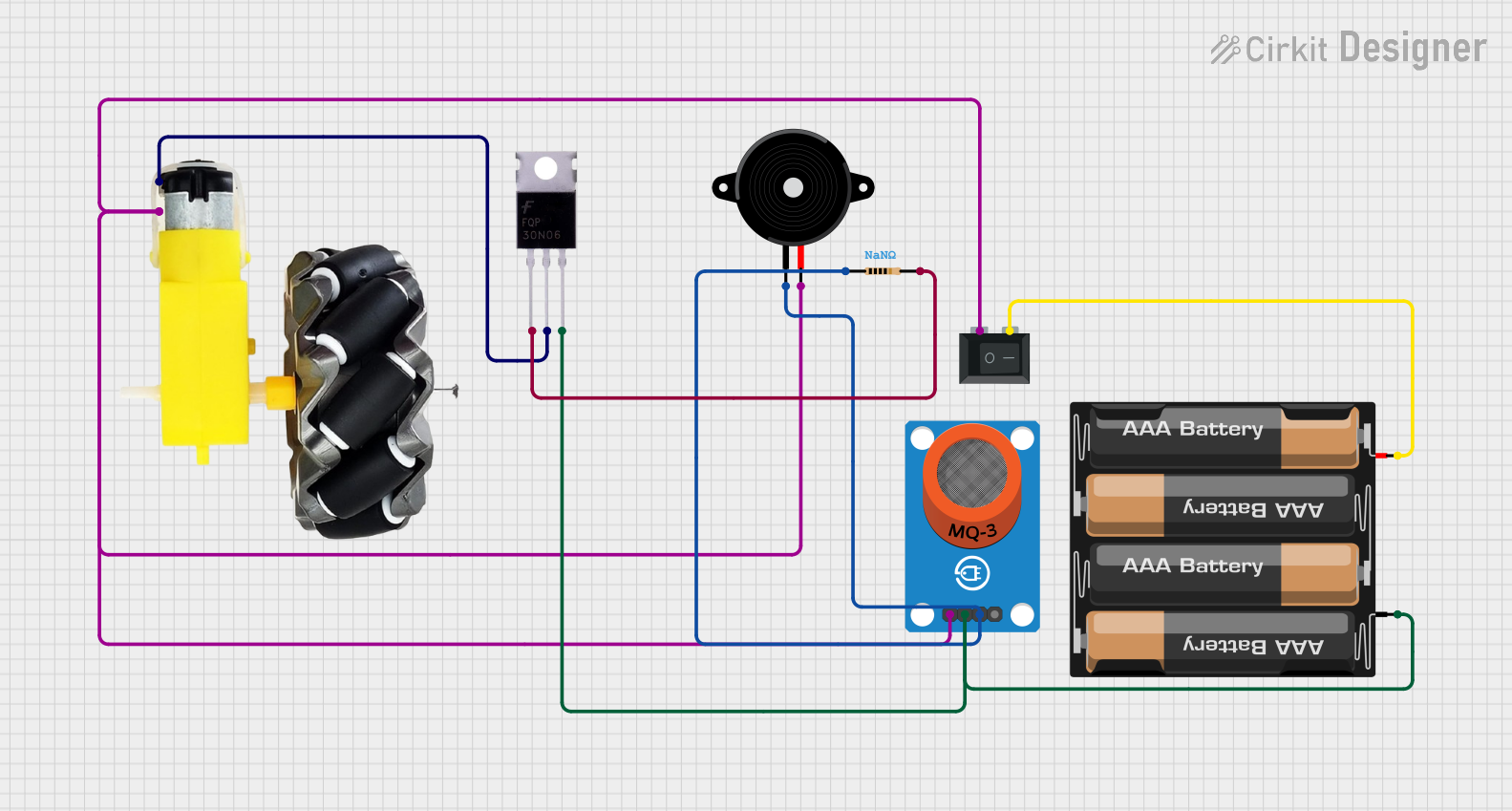
Battery-Powered Motor Control with MQ-3 Sensor and Piezo Speaker
Circuit Documentation
Summary
This document provides a detailed description of a circuit that includes a motor and wheels, a rocker switch, an MQ-3 breakout sensor, a 4 x AAA battery mount, a MOSFET, a piezo speaker, and a resistor. The circuit is designed to control the motor and wheels using the rocker switch and the MOSFET, while the MQ-3 sensor and piezo speaker provide additional functionality.
Component List
Motor and Wheels
- Pins: VCC, GND
- Description: Motor and wheels assembly for movement.
Rocker Switch (SPST)
- Pins: 1, 2
- Description: Single Pole Single Throw (SPST) switch for controlling the circuit.
MQ-3 Breakout
- Pins: VCC, GND, DO, AO
- Description: Alcohol sensor module.
4 x AAA Battery Mount
- Pins: +, -
- Description: Battery holder for four AAA batteries.
MOSFET
- Pins: Gate, Drain, Source
- Description: Metal-Oxide-Semiconductor Field-Effect Transistor for switching.
Piezo Speaker
- Pins: pin1, pin2
- Description: Speaker for sound output.
Resistor
- Pins: pin1, pin2
- Description: Resistor with unspecified resistance value.
Wiring Details
Motor and Wheels
- VCC is connected to the Drain of the MOSFET.
- GND is connected to:
- Pin 2 of the Piezo Speaker
- Pin 1 of the Rocker Switch
- VCC of the MQ-3 Breakout
Rocker Switch (SPST)
- Pin 1 is connected to:
- Pin 2 of the Piezo Speaker
- GND of the Motor and Wheels
- VCC of the MQ-3 Breakout
- Pin 2 is connected to the + of the 4 x AAA Battery Mount.
MQ-3 Breakout
- VCC is connected to:
- Pin 2 of the Piezo Speaker
- Pin 1 of the Rocker Switch
- GND of the Motor and Wheels
- GND is connected to:
- - of the 4 x AAA Battery Mount
- Source of the MOSFET
- DO is connected to:
- Pin 1 of the Resistor
- Pin 1 of the Piezo Speaker
4 x AAA Battery Mount
- + is connected to Pin 2 of the Rocker Switch.
- - is connected to:
- Source of the MOSFET
- GND of the MQ-3 Breakout
MOSFET
- Gate is connected to Pin 2 of the Resistor.
- Drain is connected to VCC of the Motor and Wheels.
- Source is connected to:
- - of the 4 x AAA Battery Mount
- GND of the MQ-3 Breakout
Piezo Speaker
- Pin 1 is connected to:
- Pin 1 of the Resistor
- DO of the MQ-3 Breakout
- Pin 2 is connected to:
- Pin 1 of the Rocker Switch
- GND of the Motor and Wheels
- VCC of the MQ-3 Breakout
Resistor
- Pin 1 is connected to:
- Pin 1 of the Piezo Speaker
- DO of the MQ-3 Breakout
- Pin 2 is connected to the Gate of the MOSFET.
Code
There is no code provided for this circuit.