
ESP32-Based Health Monitoring System with TFT Display and RTC
View and Edit Project In Cirkit Designer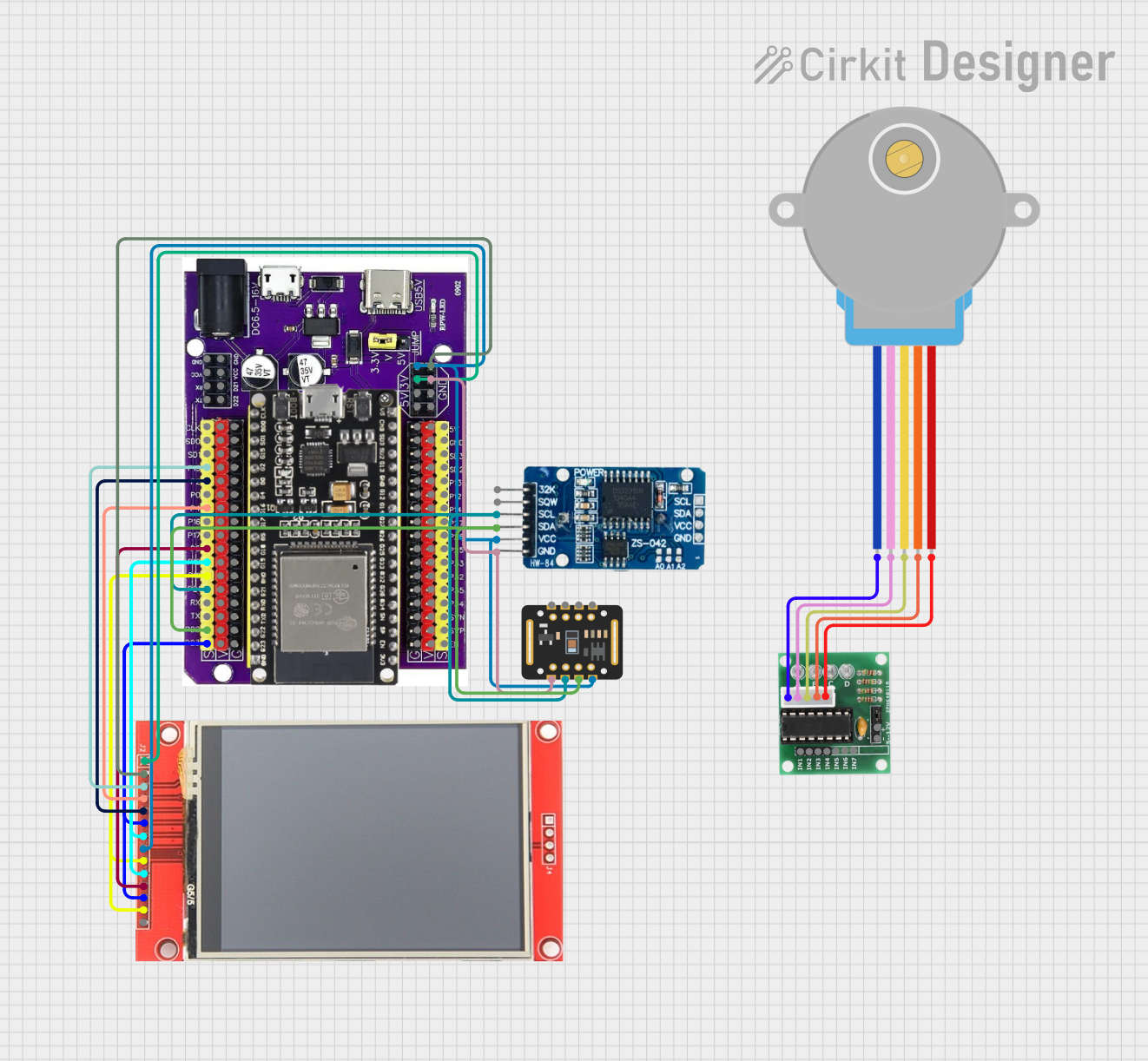
Circuit Documentation
Summary
This document provides a detailed overview of a circuit that integrates an ESP32 microcontroller with various peripherals including an ILI9341 TFT display, an RTC DS3231 module, a MAX30102 sensor, and a 28BYJ-48 stepper motor driven by a ULN2003 driver. The circuit is designed to display health data and time on the TFT display, read sensor data, and control a stepper motor.
Component List
ESP32 on Baseboard
- Description: A versatile microcontroller with built-in Wi-Fi and Bluetooth capabilities.
- Pins: GPIO23, GPIO22, GPIO1/TX, GPIO3/RX, GPIO21, GPIO19, GPIO18, GPIO5, GPIO17, GPIO16, GPIO4, GPIO0, GPIO2, GPIO15, SD1, SD0, CLK, V, G, GPIO36, GPIO39, GPIO34, GPIO35, GPIO32, GPIO33, GPIO25, GPIO26, GPIO27, GPIO14, GPIO12, GPIO13, SD2, SD3, GND, 5V, 3V, TX, RX, VCC, D22, D21
ILI9341 TFT Display
- Description: A 240x320 pixel TFT display with touch capabilities.
- Pins: VCC, GND, CS, RESET, DC/RS, SDI, SCK, LED, SDO, T_CLK, T_CS, T_DIN, T_DO, T_IRQ
RTC DS3231
- Description: A real-time clock module with a temperature-compensated crystal oscillator.
- Pins: 32K, SQW, SCL, SDA, VCC, GND
MAX30102
- Description: A pulse oximeter and heart-rate sensor module.
- Pins: VIN, SDA, SCL, GND, RD, IRD, INT
28BYJ-48 Stepper Motor
- Description: A 5V stepper motor commonly used in low-power applications.
- Pins: BLUE, PINK, YELLOW, ORANGE, RED
ULN2003
- Description: A Darlington transistor array used to drive the stepper motor.
- Pins: IN1, IN2, IN3, IN4, IN5, IN6, IN7, GND, +, COIL1, COIL2, COIL3, COIL4, COIL5
Wiring Details
ESP32 on Baseboard
- GPIO23 connected to ILI9341 TFT Display T_DIN and SDI
- GPIO22 connected to MAX30102 SDA and RTC DS3231 SDA
- GPIO21 connected to MAX30102 SCL and RTC DS3231 SCL
- GPIO19 connected to ILI9341 TFT Display T_DO and SDO
- GPIO18 connected to ILI9341 TFT Display SCK and T_CLK
- GPIO5 connected to ILI9341 TFT Display T_CS
- GPIO4 connected to ILI9341 TFT Display RESET
- GPIO2 connected to ILI9341 TFT Display DC/RS
- GPIO15 connected to ILI9341 TFT Display CS
- GND connected to MAX30102 GND, RTC DS3231 GND, and ILI9341 TFT Display GND
- 3V connected to ILI9341 TFT Display VCC, MAX30102 VIN, RTC DS3231 VCC, and ILI9341 TFT Display LED
ILI9341 TFT Display
- T_DIN connected to ESP32 GPIO23
- SDI connected to ESP32 GPIO23
- T_DO connected to ESP32 GPIO19
- SDO connected to ESP32 GPIO19
- SCK connected to ESP32 GPIO18
- T_CLK connected to ESP32 GPIO18
- T_CS connected to ESP32 GPIO5
- RESET connected to ESP32 GPIO4
- DC/RS connected to ESP32 GPIO2
- CS connected to ESP32 GPIO15
- GND connected to ESP32 GND
- VCC connected to ESP32 3V
- LED connected to ESP32 3V
RTC DS3231
- SDA connected to ESP32 GPIO22 and MAX30102 SDA
- SCL connected to ESP32 GPIO21 and MAX30102 SCL
- GND connected to ESP32 GND
- VCC connected to ESP32 3V
MAX30102
- SDA connected to ESP32 GPIO22 and RTC DS3231 SDA
- SCL connected to ESP32 GPIO21 and RTC DS3231 SCL
- GND connected to ESP32 GND
- VIN connected to ESP32 3V
28BYJ-48 Stepper Motor
- BLUE connected to ULN2003 COIL1
- PINK connected to ULN2003 COIL2
- YELLOW connected to ULN2003 COIL3
- ORANGE connected to ULN2003 COIL4
- RED connected to ULN2003 COIL5
ULN2003
- COIL1 connected to 28BYJ-48 Stepper Motor BLUE
- COIL2 connected to 28BYJ-48 Stepper Motor PINK
- COIL3 connected to 28BYJ-48 Stepper Motor YELLOW
- COIL4 connected to 28BYJ-48 Stepper Motor ORANGE
- COIL5 connected to 28BYJ-48 Stepper Motor RED
Documented Code
ESP32 on Baseboard
sketch.ino
void setup() {
  // put your setup code here, to run once:

}

void loop() {
  // put your main code here, to run repeatedly:

}
ILI9341 TFT Display
sketch.ino
#include "FS.h"
#include <SPI.h>
#include <TFT_eSPI.h>
#include <Wire.h>
#include <RTClib.h>  // Include RTC library
#include <MAX3010x.h>  // Include MAX3010x library

TFT_eSPI tft = TFT_eSPI(); // Invoke custom library
RTC_DS3231 rtc;            // Declare RTC object
MAX30105 sensor;           // Declare MAX30105 sensor

#define CALIBRATION_FILE "/TouchCalData1"
#define REPEAT_CAL false

// Button parameters
#define BTN_W 60
#define BTN_H 40
#define BTN_SPACING_X 10
#define BTN_SPACING_Y 10
#define BTN_TEXTSIZE 2

// Button labels
char dayLabel[7][10] = {"Mon", "Tue", "Wed", "Thu", "Fri", "Sat", "Sun"};
TFT_eSPI_Button dayButton[7]; // Create 7 buttons

// Display dimensions
#define SCREEN_WIDTH 240
#define SCREEN_HEIGHT 320
#define PADDING 3 // Padding for UI elements

int pulse = 0;       // Placeholder for pulse measurement
int glucose = 0;     // Placeholder for glucose measurement

//------------------------------------------------------------------------------------------

void setup() {
  Serial.begin(115200);
  tft.init();
  tft.setRotation(0); // Portrait mode

  Wire.begin(21, 22);  // Initialize I2C (SDA, SCL)
  if (!rtc.begin()) {
    Serial.println("Couldn't find RTC");
    while (1); // Halt if RTC is not found
  }

  // Initialize MAX30105 sensor
  if (!sensor.begin()) {
    Serial.println("MAX30105 not found. Please check wiring/power.");
    while (1);
  }

  touch_calibrate();
  drawUI();
}

//------------------------------------------------------------------------------------------

void loop() {
  uint16_t t_x = 0, t_y = 0;
  DateTime now = rtc.now(); // Get current time from RTC

  // Simulate readings for pulse and glucose (replace with actual sensor readings)
  pulse = random(60, 100);      // Example pulse value (replace with actual reading)
  glucose = random(80, 180);    // Example glucose value (replace with actual reading)

  // Update Date/Time and Health Data on the display
  updateDateTime(now);
  updateHealthData();

  // Check for touch input
  bool pressed = tft.getTouch(&t_x, &t_y);

  for (uint8_t b = 0; b < 7; b++) {
    if (pressed && dayButton[b].contains(t_x, t_y)) {
      dayButton[b].press(true);
    } else {
      dayButton[b].press(false);
    }
  }

  for (uint8_t b = 0; b < 7; b++) {
    if (dayButton[b].justReleased()) dayButton[b].drawButton();
    if (dayButton[b].justPressed