
Arduino Mega 2560-Based Smart Environmental Control System with DHT22 and Photocell
View and Edit Project In Cirkit Designer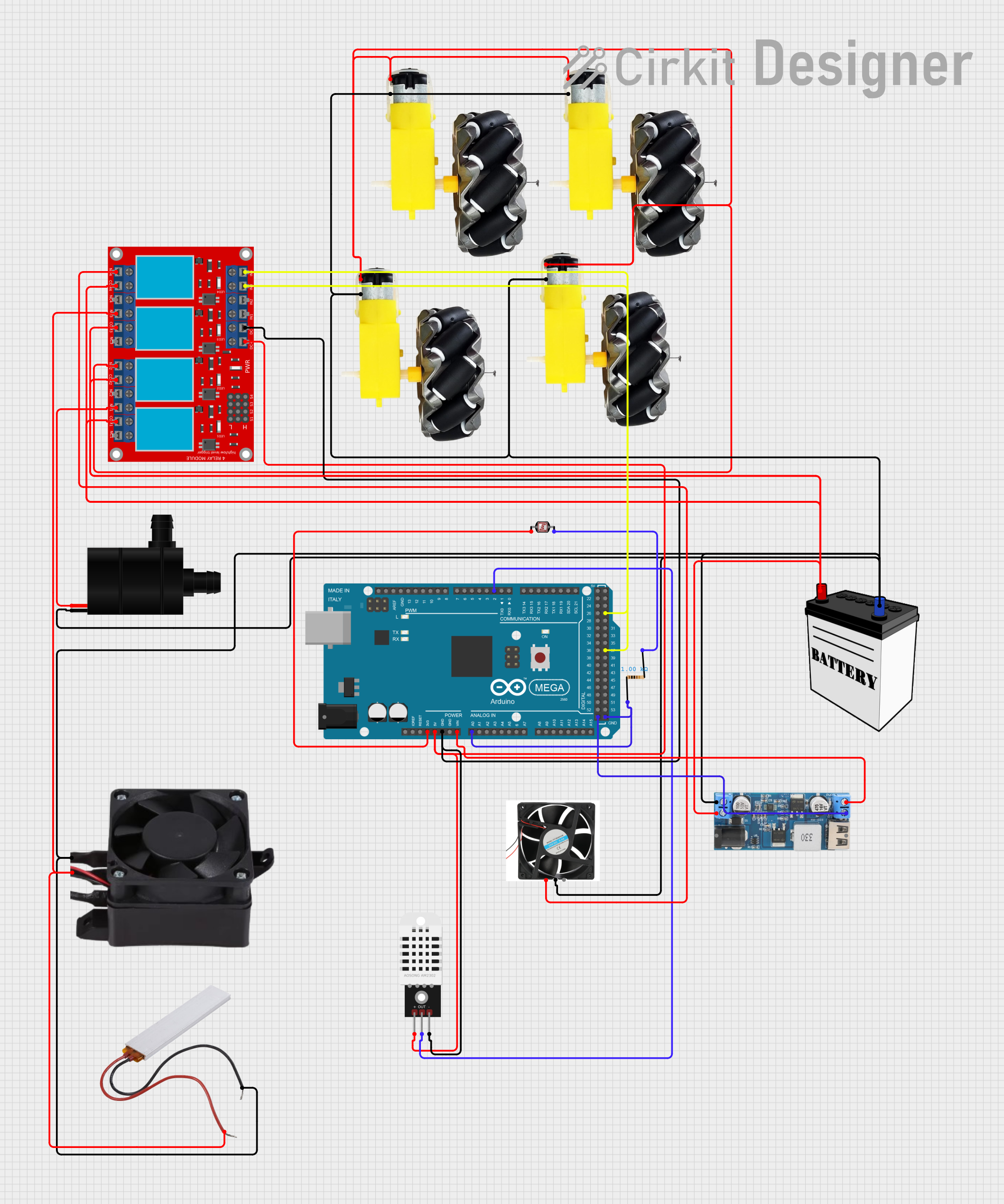
Circuit Documentation
Summary
This document provides a detailed overview of a circuit designed to monitor environmental conditions and control various actuators. The circuit includes sensors for temperature and humidity, a photocell, multiple motors, a fan heater, a water pump, and a relay module. An Arduino Mega 2560 microcontroller is used to process sensor data and control the actuators based on predefined conditions.
Component List
DHT22
- Description: Digital temperature and humidity sensor.
- Pins: +, Out, -
Photocell (LDR)
- Description: Light-dependent resistor used to measure light intensity.
- Pins: pin 0, pin 1
Motor and Wheels
- Description: DC motor with attached wheels.
- Pins: vcc, GND
12V Battery
- Description: Power source providing 12V.
- Pins: VCC, GND
Fan Heater 12V
- Description: 12V fan heater.
- Pins: Ground, 12V
Water Pump
- Description: 12V water pump.
- Pins: VCC, GND
Resistor
- Description: 1000 Ohms resistor.
- Pins: pin1, pin2
PTC
- Description: Positive temperature coefficient thermistor.
- Pins: Neutral, Live
12V to 5V Step Down Power Converter
- Description: Converts 12V input to 5V output.
- Pins: VIN 9v-36v, VIN+, VIN-, USB OUTPUT 5V, 5v OUTPUT, GND
4 Channel Relay Module
- Description: Relay module with 4 channels.
- Pins: N.O. 4, COM 4, N.C. 4, N.O. 3, COM 3, N.C. 3, N.O. 2, COM 2, N.C. 2, N.O. 1, COM 1, N.C. 1, Pin 13, Pin 14, Pin 15, Pin 16, Pin 17, Pin 18, Pin 19, Pin 20, Pin 21, Pin 22, Pin 23, Pin 24, VCC+, VCC- (GND), IN 1, IN 2, IN 3, IN 4
Fan 140mm
- Description: 140mm fan.
- Pins: 12V, GND, PWM
Arduino Mega 2560
- Description: Microcontroller board based on the ATmega2560.
- Pins: IOREF, RESET, 3V3, 5V, GND, VIN, A0, A1, A2, A3, A4, A5, A6, A7, A8, A9, A10, A11, A12, A13, A14, A15, D21/SCL, D20/SDA, D19/RX1, D18/TX1, D17 PWM/RX2, D16 PWM/TX2, D15/RX3, D14/TX3, D0 RX0, D1 TX0, D2 PWM, D3 PWM, D4 PWM, D5 PWM, D6 PWM, D7 PWM, D8 PWM, D9 PWM, D10 PWM, D11 PWM, D12 PWM, D13 PWM, AREF, SDA, SCL, D52, D50, D48, D46, D44, D42, D40, D38, D36, D34, D32, D30, D28, D26, D24, D22, D53, D51, D49, D47, D45, D43, D41, D39, D37, D35, D33, D31, D29, D27, D25, D23
Wiring Details
DHT22
- + connected to Arduino Mega 2560 5V and 4 Channel Relay Module VCC+
- - connected to Arduino Mega 2560 GND and 4 Channel Relay Module VCC- (GND)
- Out connected to Arduino Mega 2560 D2 PWM
Photocell (LDR)
- pin 0 connected to Arduino Mega 2560 3V3
- pin 1 connected to Resistor pin2
Motor and Wheels
- vcc connected to 4 Channel Relay Module N.O. 2
- GND connected to 12V Battery GND
12V Battery
- VCC connected to 12V to 5V Step Down Power Converter VIN+ and 4 Channel Relay Module COM 4, COM 1, COM 3, COM 2
- GND connected to Motor and Wheels GND, 12V to 5V Step Down Power Converter VIN-, Fan 140mm GND, PTC Neutral, Water Pump GND, Fan Heater 12V Ground
Fan Heater 12V
- Ground connected to 12V Battery GND
- 12V connected to 4 Channel Relay Module N.O. 3
Water Pump
- VCC connected to 4 Channel Relay Module N.O. 1
- GND connected to 12V Battery GND
Resistor
- pin1 connected to Arduino Mega 2560 GND and Arduino Mega 2560 A0
- pin2 connected to Photocell (LDR) pin 1
PTC
- Neutral connected to 12V Battery GND
- Live connected to 4 Channel Relay Module N.O. 3
12V to 5V Step Down Power Converter
- 5v OUTPUT connected to Arduino Mega 2560 VIN
- GND connected to Arduino Mega 2560 GND
- VIN+ connected to 12V Battery VCC
- VIN- connected to 12V Battery GND
4 Channel Relay Module
- VCC+ connected to Arduino Mega 2560 5V and DHT22 +
- VCC- (GND) connected to Arduino Mega 2560 GND and DHT22 -
- IN 3 connected to Arduino Mega 2560 D37
- IN 4 connected to Arduino Mega 2560 D27
- N.O. 4 connected to Fan 140mm 12V
- N.O. 2 connected to Motor and Wheels vcc
- N.O. 3 connected to PTC Live and Fan Heater 12V 12V
- N.O. 1 connected to Water Pump VCC
Fan 140mm
- 12V connected to 4 Channel Relay Module N.O. 4
- GND connected to 12V Battery GND
Arduino Mega 2560
- 3V3 connected to Photocell (LDR) pin 0
- 5V connected to DHT22 + and 4 Channel Relay Module VCC+
- GND connected to DHT22 -, 4 Channel Relay Module VCC- (GND), Resistor pin1, 12V to 5V Step Down Power Converter GND
- VIN connected to 12V to 5V Step Down Power Converter 5v OUTPUT
- D2 PWM connected to DHT22 Out
- D37 connected to 4 Channel Relay Module IN 3
- D27 connected to 4 Channel Relay Module IN 4
- A0 connected to Resistor pin1
Code Documentation
#include <DHT.h>

// Define pin for the DHT sensor
#define DHTPIN 2      // Pin where the DHT sensor is connected
#define DHTTYPE DHT22 // DHT 22 (AM2302) sensor

// Define the fan control pin
#define FAN_PIN 7     // Pin to control the exhaust fan (e.g., through a relay or transistor)
#define FAN_exst 27

// Initialize the DHT sensor
DHT dht(DHTPIN, DHTTYPE);

void setup() {
  // Start the serial communication
  pinMode(FAN_exst,OUTPUT);
  Serial.begin(9600);

  // Initialize the DHT sensor
  dht.begin();

  // Set the fan control pin as an output
  pinMode(FAN_PIN, OUTPUT);

  // Initially, turn off the fan
  digitalWrite(FAN_PIN, LOW);
}

void loop() {
  // Wait a few seconds between readings
  delay(2000);

  // Get humidity and temperature values from the DHT sensor
  float humidity = dht.read