
Arduino UNO Dual Stepper Motor Controller with LED Indicator
View and Edit Project In Cirkit Designer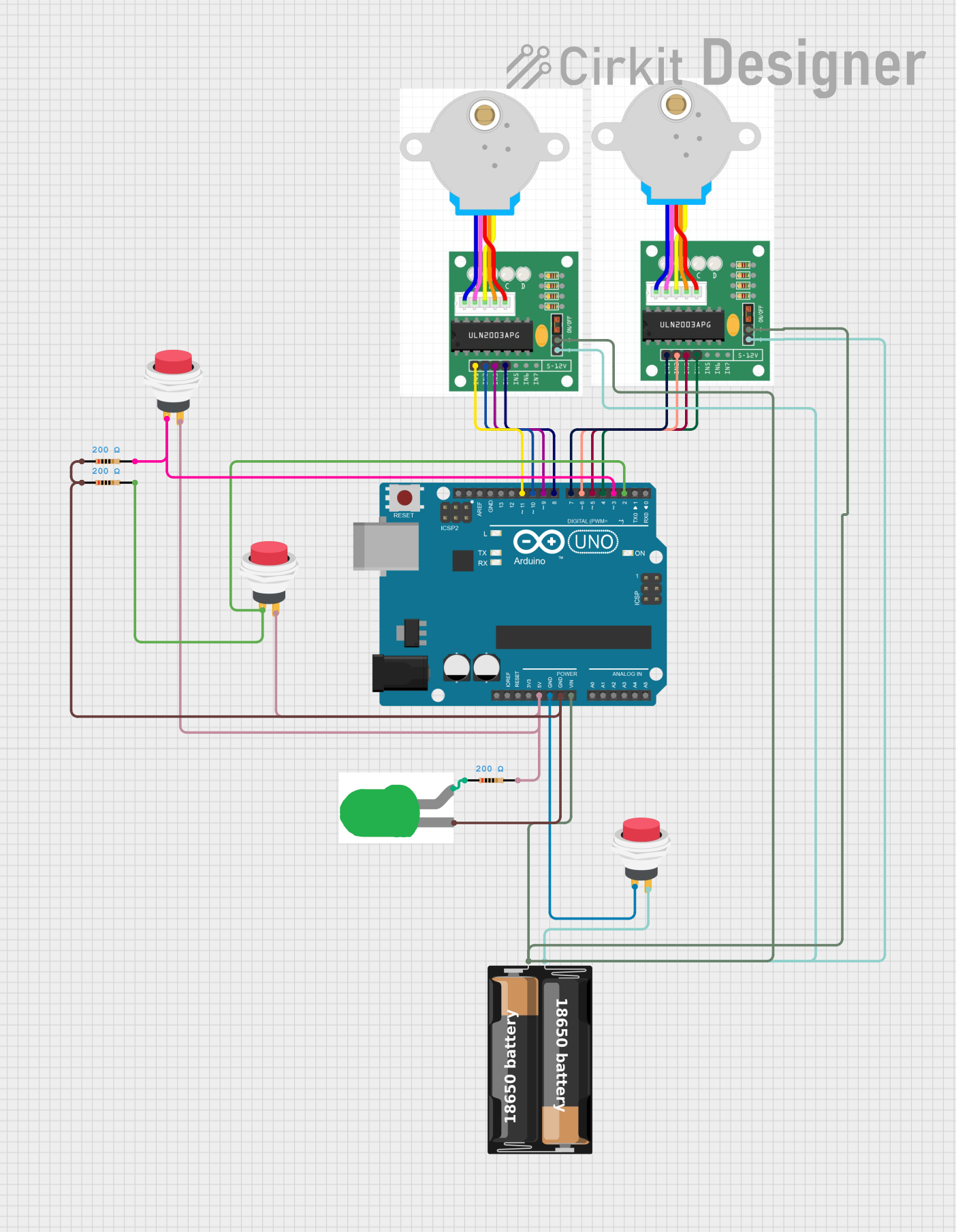
Circuit Documentation
Summary
This circuit involves an Arduino UNO microcontroller, two stepper motors, a green LED, resistors, push switches, and a battery case. The Arduino UNO controls the stepper motors and the LED, while the push switches are used to interact with the circuit. The battery case provides power to the stepper motors.
Component List
Arduino UNO
- Description: Microcontroller board based on the ATmega328P.
- Pins: UNUSED, IOREF, Reset, 3.3V, 5V, GND, Vin, A0, A1, A2, A3, A4, A5, SCL, SDA, AREF, D13, D12, D11, D10, D9, D8, D7, D6, D5, D4, D3, D2, D1, D0
Stepper Motor One
- Description: Stepper motor with four control pins and two power pins.
- Pins: IN1, IN2, IN3, IN4, +, -
Stepper Motor Two
- Description: Stepper motor with four control pins and two power pins.
- Pins: IN1, IN2, IN3, IN4, +, -
2Pin Push Switch
- Description: Push switch with two pins.
- Pins: Input +, Output +
Battery Case
- Description: Battery case with two pins for power supply.
- Pins: +, -
LED: Two Pin (Green)
- Description: Green LED with two pins.
- Pins: cathode, anode
Resistor (200 Ohms)
- Description: Resistor with a resistance of 200 Ohms.
- Pins: pin1, pin2
Wiring Details
Arduino UNO
- 5V: Connected to pin2 of a resistor and Output + of two push switches.
- GND: Connected to Input + of a push switch, cathode of the LED, and pin1 of two resistors.
- Vin: Connected to + of both stepper motors and + of the battery case.
- D11: Connected to IN1 of stepper motor one.
- D10: Connected to IN2 of stepper motor one.
- D9: Connected to IN3 of stepper motor one.
- D8: Connected to IN4 of stepper motor one.
- D7: Connected to IN1 of stepper motor two.
- D6: Connected to IN2 of stepper motor two.
- D5: Connected to IN3 of stepper motor two.
- D4: Connected to IN4 of stepper motor two.
- D3: Connected to pin2 of a resistor and Input + of a push switch.
- D2: Connected to Input + of a push switch and pin2 of a resistor.
Stepper Motor One
- IN1: Connected to D11 of the Arduino UNO.
- IN2: Connected to D10 of the Arduino UNO.
- IN3: Connected to D9 of the Arduino UNO.
- IN4: Connected to D8 of the Arduino UNO.
- +: Connected to Vin of the Arduino UNO and + of the battery case.
- -: Connected to Output + of a push switch and - of the battery case.
Stepper Motor Two
- IN1: Connected to D7 of the Arduino UNO.
- IN2: Connected to D6 of the Arduino UNO.
- IN3: Connected to D5 of the Arduino UNO.
- IN4: Connected to D4 of the Arduino UNO.
- +: Connected to Vin of the Arduino UNO and + of the battery case.
- -: Connected to Output + of a push switch and - of the battery case.
2Pin Push Switch
- Input +: Connected to GND of the Arduino UNO.
- Output +: Connected to pin2 of a resistor and 5V of the Arduino UNO.
Battery Case
- +: Connected to Vin of the Arduino UNO and + of both stepper motors.
- -: Connected to Output + of a push switch and - of both stepper motors.
LED: Two Pin (Green)
- cathode: Connected to GND of the Arduino UNO.
- anode: Connected to pin1 of a resistor.
Resistor (200 Ohms)
- pin1: Connected to anode of the LED.
- pin2: Connected to 5V of the Arduino UNO and Output + of two push switches.
Code Documentation
Arduino UNO Code
sketch.ino
void setup() {
  // put your setup code here, to run once:

}

void loop() {
  // put your main code here, to run repeatedly:

}
documentation.txt