
Arduino Mega 2560-Based Heart Rate and SpO2 Monitor with MAX30102 Sensor
View and Edit Project In Cirkit Designer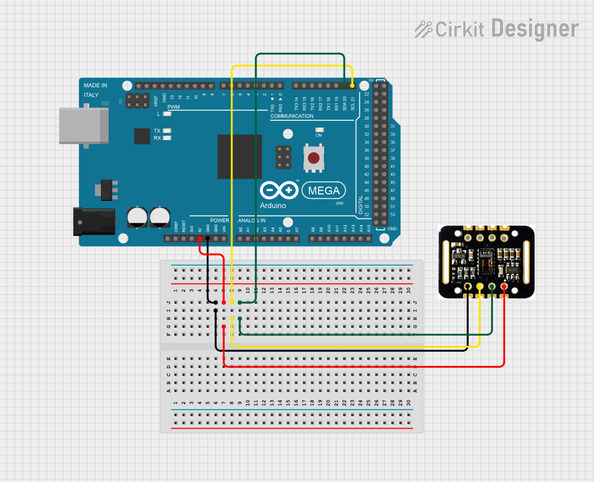
Circuit Documentation
Summary
This document provides a detailed overview of a circuit that includes an Arduino Mega 2560 microcontroller and a MAX30102 HR + SpO2 sensor. The Arduino Mega 2560 is used to interface with the MAX30102 sensor to measure heart rate and blood oxygen levels. The document includes a list of components, wiring details, and the embedded code used in the microcontroller.
Component List
Arduino Mega 2560
- Description: A microcontroller board based on the ATmega2560.
- Pins: IOREF, RESET, 3V3, 5V, GND, VIN, A0, A1, A2, A3, A4, A5, A6, A7, A8, A9, A10, A11, A12, A13, A14, A15, D21/SCL, D20/SDA, D19/RX1, D18/TX1, D17 PWM/RX2, D16 PWM/TX2, D15/RX3, D14/TX3, D0 RX0, D1 TX0, D2 PWM, D3 PWM, D4 PWM, D5 PWM, D6 PWM, D7 PWM, D8 PWM, D9 PWM, D10 PWM, D11 PWM, D12 PWM, D13 PWM, AREF, SDA, SCL, D52, D50, D48, D46, D44, D42, D40, D38, D36, D34, D32, D30, D28, D26, D24, D22, D53, D51, D49, D47, D45, D43, D41, D39, D37, D35, D33, D31, D29, D27, D25, D23, 6swdw
MAX30102 HR + SpO2 sensor
- Description: A sensor module used for measuring heart rate and blood oxygen levels.
- Pins: INT, IRD, RD, GND, SCL, SDA, VIN
Wiring Details
Arduino Mega 2560
- GND is connected to GND of the MAX30102 HR + SpO2 sensor.
- 5V is connected to VIN of the MAX30102 HR + SpO2 sensor.
- D21/SCL is connected to SCL of the MAX30102 HR + SpO2 sensor.
- D20/SDA is connected to SDA of the MAX30102 HR + SpO2 sensor.
MAX30102 HR + SpO2 sensor
- GND is connected to GND of the Arduino Mega 2560.
- VIN is connected to 5V of the Arduino Mega 2560.
- SCL is connected to D21/SCL of the Arduino Mega 2560.
- SDA is connected to D20/SDA of the Arduino Mega 2560.
Code Documentation
Arduino Mega 2560 Code
void setup() {
  // put your setup code here, to run once:

}

void loop() {
  // put your main code here, to run repeatedly:

}
This code is a basic template for the Arduino Mega 2560. The setup() function is where you initialize your sensor and any other peripherals. The loop() function is where you will write the main logic to read data from the MAX30102 sensor and process it.
Additional Documentation
This section is reserved for any additional documentation or notes that may be required for understanding the circuit and its operation.