
Circuit Documentation
Summary of the Circuit
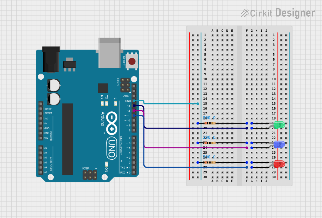
This circuit is designed around an Arduino UNO microcontroller and includes three LEDs (green, blue, and red) each with a corresponding resistor. The purpose of the circuit is to sequentially light up each LED for a short duration and then turn them off in the same order. This is achieved through digital pins D13, D12, and D11 of the Arduino UNO, which are connected to the anodes of the green, blue, and red LEDs, respectively. The cathodes of the LEDs are connected to ground (GND) through 200 Ohm resistors to limit the current through the LEDs.
Component List
Arduino UNO
- Description: A microcontroller board based on the ATmega328P.
- Pins: UNUSED, IOREF, Reset, 3.3V, 5V, GND, Vin, A0-A5, SCL, SDA, AREF, D0-D13
LED: Two Pin (green)
- Description: A green light-emitting diode.
- Pins: cathode, anode
LED: Two Pin (blue)
- Description: A blue light-emitting diode.
- Pins: cathode, anode
LED: Two Pin (red)
- Description: A red light-emitting diode.
- Pins: cathode, anode
Resistor (200 Ohms)
- Description: A resistor with a resistance of 200 Ohms.
- Pins: pin1, pin2
Wiring Details
Arduino UNO
- D13 connected to the anode of the green LED.
- D12 connected to the anode of the blue LED.
- D11 connected to the anode of the red LED.
- GND connected to pin1 of all three resistors.
LED: Two Pin (green)
- Anode connected to D13 of the Arduino UNO.
- Cathode connected to pin2 of its corresponding 200 Ohm resistor.
LED: Two Pin (blue)
- Anode connected to D12 of the Arduino UNO.
- Cathode connected to pin2 of its corresponding 200 Ohm resistor.
LED: Two Pin (red)
- Anode connected to D11 of the Arduino UNO.
- Cathode connected to pin2 of its corresponding 200 Ohm resistor.
Resistor (200 Ohms)
- Pin1 connected to GND of the Arduino UNO.
- Pin2 connected to the cathode of the corresponding LED.
Documented Code
// Code for controlling three LEDs with an Arduino UNO
int LED1 = 13; // Green LED connected to pin D13
int LED2 = 12; // Blue LED connected to pin D12
int LED3 = 11; // Red LED connected to pin D11

void setup() {
  // Set LED pins as outputs
  pinMode(LED1, OUTPUT);
  pinMode(LED2, OUTPUT);
  pinMode(LED3, OUTPUT);
}

void loop() {
  // Turn on the green LED
  digitalWrite(LED1, HIGH);
  delay(200); // Wait for 200ms
  // Turn on the blue LED
  digitalWrite(LED2, HIGH);
  delay(200); // Wait for 200ms
  // Turn on the red LED
  digitalWrite(LED3, HIGH);
  delay(200); // Wait for 200ms

  // Turn off the green LED
  digitalWrite(LED1, LOW);
  delay(300); // Wait for 300ms
  // Turn off the blue LED
  digitalWrite(LED2, LOW);
  delay(300); // Wait for 300ms
  // Turn off the red LED
  digitalWrite(LED3, LOW);
  delay(300); // Wait for 300ms
}
Note: The code provided has syntax errors with extra periods in the digitalWrite function calls. These should be removed for the code to compile and run correctly.