
Circuit Documentation
Summary
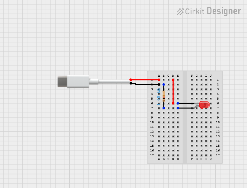
This document provides a detailed description of a simple electronic circuit consisting of a Type C port, a resistor, and a red LED. The circuit is designed to power the LED through the resistor when connected to a power source via the Type C port.
Component List
Type C Port
- Description: A standard USB Type C port used to provide power to the circuit.
- Pins: Negative, Positive
Resistor
- Description: A resistor with a resistance of 1000 Ohms.
- Pins: pin1, pin2
- Properties:
- Resistance: 1000 Ohms
LED: Two Pin (red)
- Description: A red LED with two pins: cathode and anode.
- Pins: cathode, anode
Wiring Details
Type C Port
- Negative Pin:
- Connected to the cathode pin of the red LED.
- Positive Pin:
- Connected to pin2 of the resistor.
Resistor
- pin1:
- Connected to the anode pin of the red LED.
- pin2:
- Connected to the Positive pin of the Type C port.
LED: Two Pin (red)
- cathode:
- Connected to the Negative pin of the Type C port.
- anode:
- Connected to pin1 of the resistor.
Code
There is no microcontroller code associated with this circuit.
This document provides a comprehensive overview of the components and their connections within the circuit. The circuit is designed to light up the red LED when power is supplied through the Type C port, with the resistor limiting the current to protect the LED.