
Arduino UNO Load Cell Weight Measurement System with HX711 Interface
View and Edit Project In Cirkit Designer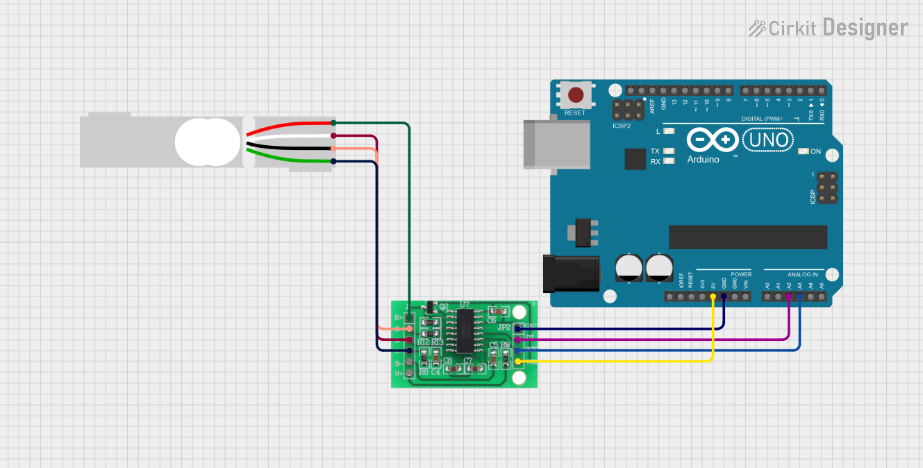
Circuit Documentation
Summary
This circuit involves an Arduino UNO microcontroller interfacing with an HX711 bridge sensor interface and a load cell. The Arduino UNO provides power and ground connections to the HX711, and it also communicates with the HX711 via data and clock lines. The HX711 is connected to a load cell to measure weight.
Component List
Arduino UNO
- Description: A microcontroller board based on the ATmega328P.
- Pins: UNUSED, IOREF, Reset, 3.3V, 5V, GND, Vin, A0, A1, A2, A3, A4, A5, SCL, SDA, AREF, D13, D12, D11, D10, D9, D8, D7, D6, D5, D4, D3, D2, D1, D0
HX711 - Bridge Sensor Interface
- Description: A precision 24-bit analog-to-digital converter (ADC) designed for weigh scales and industrial control applications.
- Pins: E+, E-, A-, A+, B-, B+, GND - GROUND, DATA (OUT), SCK - CLOCK (IN), 3.3/3.5V Supply
Load Cell - Red/white/black/green
- Description: A sensor used to measure weight or force.
- Pins: E+, A-, E-, A+
Wiring Details
Arduino UNO
- 5V connected to 3.3/3.5V Supply of HX711
- GND connected to GND - GROUND of HX711
- A2 connected to DATA (OUT) of HX711
- A3 connected to SCK - CLOCK (IN) of HX711
HX711 - Bridge Sensor Interface
- 3.3/3.5V Supply connected to 5V of Arduino UNO
- GND - GROUND connected to GND of Arduino UNO
- DATA (OUT) connected to A2 of Arduino UNO
- SCK - CLOCK (IN) connected to A3 of Arduino UNO
- E+ connected to E+ of Load Cell
- E- connected to E- of Load Cell
- A- connected to A- of Load Cell
- A+ connected to A+ of Load Cell
Load Cell - Red/white/black/green
- E+ connected to E+ of HX711
- E- connected to E- of HX711
- A- connected to A- of HX711
- A+ connected to A+ of HX711
Code Documentation
Arduino UNO Code
sketch.ino
void setup() {
  // put your setup code here, to run once:

}

void loop() {
  // put your main code here, to run repeatedly:

}
documentation.txt