Arduino UNO Temperature-Controlled Fan with LCD Display and Battery Power
Circuit Documentation
Summary
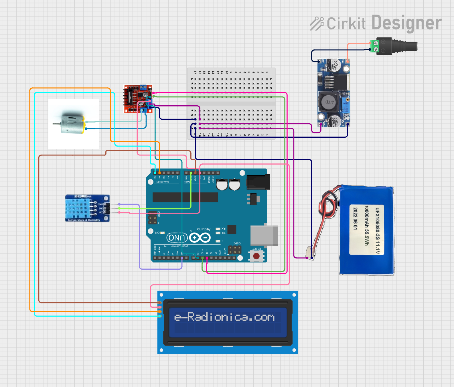
This circuit is designed to monitor temperature using a DHT11 sensor and display the temperature on a 16x2 I2C LCD screen. Based on the temperature readings, it controls the speed of a fan motor using an L298N motor driver. The entire system is powered by a 10000mAh Lithium-ion battery, with voltage regulation provided by a 48V to 5V converter. The Arduino UNO microcontroller is the central unit that processes the sensor data and controls the motor and LCD.
Component List
Arduino UNO
- Description: Microcontroller board based on the ATmega328P.
- Pins: UNUSED, IOREF, Reset, 3.3V, 5V, GND, Vin, A0, A1, A2, A3, A4, A5, SCL, SDA, AREF, D13, D12, D11, D10, D9, D8, D7, D6, D5, D4, D3, D2, D1, D0
L298N Motor Driver Controller Board Module Stepper Motor
- Description: Dual H-Bridge motor driver for controlling DC and stepper motors.
- Pins: Output A, +12v Power, +5v Power, Ground, Output B, Input 4, Input 3, Input 2, Input 1
DHT11
- Description: Temperature and humidity sensor.
- Pins: DATA, GND, VCC
LCD screen 16x2 I2C
- Description: 16x2 character LCD display with I2C interface.
- Pins: SCL, SDA, VCC, GND
Lithium-ion Battery 10000mAh
- Description: Rechargeable battery for powering the circuit.
- Pins: 11.1V, GND
48V to 5V Converter
- Description: Voltage regulator to step down from 48V to 5V.
- Pins: out+, out--, in+, in--
2.1mm Barrel Jack with Terminal Block
- Description: Power connector for the battery.
- Pins: POS, NEG
Motor
- Description: DC motor for the fan.
- Pins: negative, positive
Wiring Details
Arduino UNO
- 5V connected to VCC of LCD screen 16x2 I2C, VCC of DHT11, and +5v Power of L298N Motor Driver.
- GND connected to GND of LCD screen 16x2 I2C and GND of DHT11.
- A4 connected to SDA of LCD screen 16x2 I2C.
- A5 connected to SCL of LCD screen 16x2 I2C.
- D11 connected to Input 3 of L298N Motor Driver.
- D10 connected to Input 2 of L298N Motor Driver.
- D9 connected to Input 1 of L298N Motor Driver.
- D6 connected to DATA of DHT11.
L298N Motor Driver Controller Board Module Stepper Motor
- +5v Power connected to 5V of Arduino UNO.
- Ground connected to GND of Arduino UNO.
- Input 3 connected to D11 of Arduino UNO.
- Input 2 connected to D10 of Arduino UNO.
- Input 1 connected to D9 of Arduino UNO.
- Output A connected to positive and negative of Motor.
- +12v Power connected to out+ of 48V to 5V Converter.
- Ground connected to out-- of 48V to 5V Converter.
DHT11
- VCC connected to 5V of Arduino UNO.
- GND connected to GND of Arduino UNO.
- DATA connected to D6 of Arduino UNO.
LCD screen 16x2 I2C
- VCC connected to 5V of Arduino UNO.
- GND connected to GND of Arduino UNO.
- SDA connected to A4 of Arduino UNO.
- SCL connected to A5 of Arduino UNO.
Lithium-ion Battery 10000mAh
- 11.1V connected to out+ of 48V to 5V Converter.
- GND connected to out-- of 48V to 5V Converter.
48V to 5V Converter
- out+ connected to +12v Power of L298N Motor Driver and 11.1V of Lithium-ion Battery.
- out-- connected to Ground of L298N Motor Driver and GND of Lithium-ion Battery.
- in+ connected to POS of 2.1mm Barrel Jack with Terminal Block.
- in-- connected to NEG of 2.1mm Barrel Jack with Terminal Block.
2.1mm Barrel Jack with Terminal Block
- POS connected to in+ of 48V to 5V Converter.
- NEG connected to in-- of 48V to 5V Converter.
Motor
- positive connected to Output A of L298N Motor Driver.
- negative connected to Output A of L298N Motor Driver.
Documented Code
#include <Adafruit_Sensor.h>
#include <DHT.h>
#include <DHT_U.h>
#include <Wire.h>
#include <LiquidCrystal_I2C.h>

#define DHTPIN 6
#define DHTTYPE DHT11

#define MOTOR_PIN_ENA 9
#define MOTOR_PIN_IN1 10
#define MOTOR_PIN_IN2 11

#define TEMPERATURE_THRESHOLD 28
#define TEMPERATURE_THRESHOLD1 32

DHT dht(DHTPIN, DHTTYPE);

LiquidCrystal_I2C lcd(0x27, 16, 2);

void setup() {
  Serial.begin(9600);
  dht.begin();

  Wire.begin();
  lcd.init();
  lcd.backlight();
  lcd.begin(16, 2);
  lcd.setCursor(0, 0);
  lcd.print("Temperature:");
}

void loop() {
  delay(2000);

  float temperature = dht.readTemperature();
  if (isnan(temperature)) {
    Serial.println("Failed to read temperature from DHT sensor!");
    return;
  }

  Serial.print("Temperature: ");
  Serial.print(temperature);
  Serial.println(" °C");

  lcd.setCursor(0, 1);
  lcd.print("                ");

  if (temperature > TEMPERATURE_THRESHOLD1) {
    analogWrite(MOTOR_PIN_ENA, 255);
    digitalWrite(MOTOR_PIN_IN1, HIGH);
    digitalWrite(MOTOR_PIN_IN2, LOW);
    lcd.setCursor(0, 1);
    lcd.print("FAN Speed: Max");
  }
  else if (temperature > TEMPERATURE_THRESHOLD) {
    analogWrite(MOTOR_PIN_ENA, 100);
    digitalWrite(MOTOR_PIN_IN1, HIGH);
    digitalWrite(MOTOR_PIN_IN2, LOW);
    lcd.setCursor(0, 1);
    lcd.print("FAN Speed: Med");
  }
  else {
    analogWrite(MOTOR_PIN_ENA, 45);
    digitalWrite(MOTOR_PIN_IN1, HIGH);
    digitalWrite(MOTOR_PIN_IN2, LOW);
    lcd.setCursor(0, 1);
    lcd.print("FAN Speed: Low");
  }

  lcd.setCursor(12, 0);
  lcd.print(temperature);
}
This code initializes the DHT11 sensor and the LCD screen, reads the temperature from the sensor, and adjusts the fan speed based on the temperature. The temperature is displayed on the LCD screen, and the fan speed is controlled using the L298N motor driver.