
NodeMCU ESP8266 Water Flow Monitoring System with OLED Display and Alert Indicators
View and Edit Project In Cirkit Designer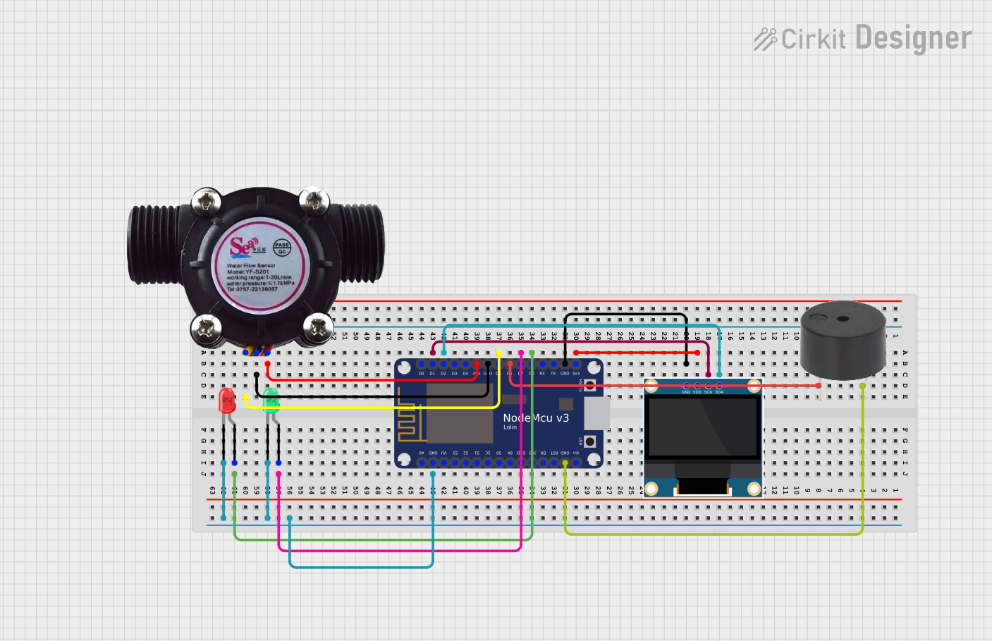
Circuit Documentation
Summary of the Circuit
This circuit is designed around the NodeMCU V3 ESP8266 microcontroller and includes a variety of peripheral components to demonstrate a range of functionalities. The peripherals include a water flow sensor for measuring the flow rate of liquids, a 0.96" OLED display for data visualization, a buzzer for audio feedback, and two LEDs (red and green) for visual status indicators. The circuit is powered by the NodeMCU's 3.3V output, and the ground connections are shared across all components. The OLED display is interfaced with the NodeMCU via I2C communication, while the water flow sensor and the LEDs are connected to digital pins for input and output operations, respectively.
Component List
NodeMCU V3 ESP8266
- Microcontroller with WiFi capability
- Pins: A0, GND, VU, S3, S2, S1, SC, S0, SK, 3V3, EN, RST, Vin, D0, D1, D2, D3, D4, D5, D6, D7, D8, RX, TX
Water Flow Sensor
- Sensor for measuring the flow rate of water
- Pins: Signal, Vcc, GND
0.96" OLED
- Small display for showing text and graphics
- Pins: GND, VDD, SCK, SDA
Buzzer
- Audio signaling device
- Pins: PIN, GND
LED: Two Pin (red)
- Red light-emitting diode for visual indication
- Pins: cathode, anode
LED: Two Pin (green)
- Green light-emitting diode for visual indication
- Pins: cathode, anode
Wiring Details
NodeMCU V3 ESP8266
- GND connected to the ground pins of the buzzer, OLED, water flow sensor, and both LEDs
- 3V3 connected to the VDD of the OLED and the Vcc of the water flow sensor
- D6 connected to the PIN of the buzzer
- D2 (SDA) and D1 (SCK) connected to the SDA and SCK of the OLED, respectively
- D8 connected to the anode of the red LED
- D7 connected to the anode of the green LED
- D5 connected to the Signal pin of the water flow sensor
Water Flow Sensor
- Signal connected to D5 on the NodeMCU
- Vcc connected to 3V3 on the NodeMCU
- GND connected to GND on the NodeMCU
0.96" OLED
- SDA connected to D2 on the NodeMCU
- SCK connected to D1 on the NodeMCU
- VDD connected to 3V3 on the NodeMCU
- GND connected to GND on the NodeMCU
Buzzer
- PIN connected to D6 on the NodeMCU
- GND connected to GND on the NodeMCU
LED: Two Pin (red)
- Anode connected to D8 on the NodeMCU
- Cathode connected to GND on the NodeMCU
LED: Two Pin (green)
- Anode connected to D7 on the NodeMCU
- Cathode connected to GND on the NodeMCU
Documented Code
No code has been provided for the microcontroller. To fully utilize the circuit's capabilities, embedded code should be written to handle the following tasks:
- Read data from the water flow sensor and display the flow rate on the OLED.
- Use the buzzer to alert when certain flow conditions are met (e.g., flow too high or too low).
- Control the red and green LEDs to indicate the system status (e.g., green for normal operation, red for alert conditions).
The code should be structured to initialize the peripherals, handle the main loop with sensor readings and display updates, and include functions for controlling the buzzer and LEDs based on the sensor's input.