
ESP32 and TEA5767 FM Radio with ILI9341 Display and Potentiometer Tuning
View and Edit Project In Cirkit Designer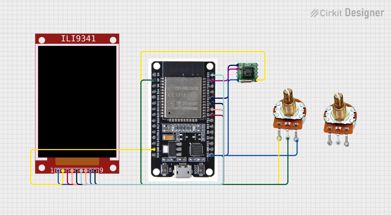
Circuit Documentation
Summary
This circuit integrates an ESP32 microcontroller, a TEA5767 FM radio module, an ILI9341 TFT display, and a rotary potentiometer. The ESP32 controls the FM radio module and displays the current frequency on the TFT display. The rotary potentiometer is used to adjust the frequency.
Component List
TEA5767
- Description: FM radio module
- Pins: SDA, SCL, BUS MODE, W/R, VCC, GND, Right Speaker OUT, Left Speaker OUT, MPXO, ANTENNA
ESP32
- Description: Microcontroller with Wi-Fi and Bluetooth capabilities
- Pins: EN, VP, VN, D34, D35, D32, D33, D25, D26, D27, D14, D12, D13, GND, VIN, 3V3, D15, D2, D4, RX2, TX2, D5, D18, D19, D21, RX0, TX0, D22, D23, BOOT
ILI9341
- Description: 2.8" TFT display with SPI interface
- Pins: VCC, GND, CS, RST, D/C, MOSI, SCK, LED, MISO
PR-Rotary Potentiometer
- Description: Rotary potentiometer for analog input
- Pins: GND, OUT, VCC
Wiring Details
TEA5767
- SDA connected to ESP32 D21
- SCL connected to ESP32 D22
- VCC connected to ESP32 3V3
- GND connected to ESP32 GND
ESP32
- D21 connected to TEA5767 SDA
- D22 connected to TEA5767 SCL
- 3V3 connected to TEA5767 VCC, ILI9341 VCC, ILI9341 LED, PR-Rotary Potentiometer VCC
- GND connected to TEA5767 GND, ILI9341 GND, PR-Rotary Potentiometer GND
- VP connected to PR-Rotary Potentiometer OUT
- D5 connected to ILI9341 CS
- D18 connected to ILI9341 RST, ILI9341 SCK
- D19 connected to ILI9341 D/C, ILI9341 MISO
- D23 connected to ILI9341 MOSI
ILI9341
- VCC connected to ESP32 3V3
- GND connected to ESP32 GND
- CS connected to ESP32 D5
- RST connected to ESP32 D18
- D/C connected to ESP32 D19
- MOSI connected to ESP32 D23
- SCK connected to ESP32 D18
- LED connected to ESP32 3V3
- MISO connected to ESP32 D19
PR-Rotary Potentiometer
- GND connected to ESP32 GND
- OUT connected to ESP32 VP
- VCC connected to ESP32 3V3
Code Documentation
ESP32 Code
#include <Wire.h>
#include <Adafruit_GFX.h>
#include <Adafruit_ILI9341.h>

#define TEA5767_I2C_ADDRESS 0x60
#define POT_PIN VP // Analog pin connected to potentiometer

// Define ILI9341 pins
#define TFT_CS   5
#define TFT_RST  18
#define TFT_DC   19
#define TFT_MOSI 23
#define TFT_CLK  18
#define TFT_MISO 19

Adafruit_ILI9341 tft = Adafruit_ILI9341(TFT_CS, TFT_DC, TFT_RST);

void setup() {
  Wire.begin();
  Serial.begin(115200);
  tft.begin();
  tft.setRotation(3);
  tft.fillScreen(ILI9341_BLACK);
  tft.setTextColor(ILI9341_WHITE);
  tft.setTextSize(2);
}

void loop() {
  int potValue = analogRead(POT_PIN);
  float frequency = map(potValue, 0, 4095, 875, 1080) / 10.0; // Map to FM frequency range 87.5 - 108.0 MHz
  setFrequency(frequency);
  displayFrequency(frequency);
  delay(1000); // Update frequency every second
}

void setFrequency(float frequency) {
  uint16_t frequencyB = (4 * (frequency * 1000000 + 225000)) / 32768;
  byte frequencyH = frequencyB >> 8;
  byte frequencyL = frequencyB & 0xFF;

  Wire.beginTransmission(TEA5767_I2C_ADDRESS);
  Wire.write(frequencyH);
  Wire.write(frequencyL);
  Wire.write(0xB0); // High side LO injection
  Wire.write(0x10); // Mute off
  Wire.write(0x00); // No search mode
  Wire.endTransmission();
}

void displayFrequency(float frequency) {
  tft.fillScreen(ILI9341_BLACK);
  tft.setCursor(0, 0);
  tft.print("Frequency: ");
  tft.print(frequency);
  tft.print(" MHz");
}
This code initializes the ESP32, sets up the ILI9341 display, and reads the analog value from the potentiometer to adjust the frequency of the TEA5767 FM radio module. The current frequency is displayed on the TFT screen.