
Arduino-Controlled 12V LED Blinker with ULN2803 Darlington Array
View and Edit Project In Cirkit Designer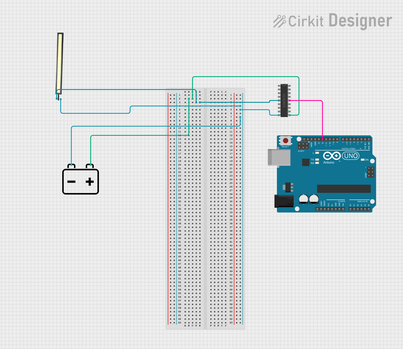
Circuit Documentation
Summary of the Circuit
This circuit is designed to control a 12V LED using an Arduino UNO microcontroller and a ULN2803 Darlington Array. The LED is powered by a 12V battery. The Arduino UNO is programmed to toggle the LED on and off by sending a signal to the ULN2803, which in turn switches the LED. The ULN2803 Darlington Array is used to handle the higher voltage and current required by the LED that the Arduino cannot directly handle.
Component List
Arduino UNO
- Description: A microcontroller board based on the ATmega328P.
- Purpose: To control the LED through digital signals.
ULN2803 Darlington Array
- Description: An 8-channel Darlington transistor array for driving high-current loads.
- Purpose: To switch the 12V LED on and off as per the control signal from the Arduino UNO.
12V Battery
- Description: A power source providing 12 volts.
- Purpose: To supply power to the LED and the common pin of the ULN2803 Darlington Array.
12V LED
- Description: A light-emitting diode designed to operate at 12 volts.
- Purpose: To emit light when powered, indicating the output state of the circuit.
Wiring Details
Arduino UNO
- Digital Pin 12: Connected to the input I5 of the ULN2803 Darlington Array.
ULN2803 Darlington Array
- COMMON: Connected to the positive terminal of the 12V Battery.
- I5: Connected to Digital Pin 12 of the Arduino UNO.
- O5: Connected to the positive terminal of the 12V LED.
- GND: Connected to the negative terminal of the 12V Battery.
12V Battery
- Positive Terminal: Connected to the COMMON pin of the ULN2803 Darlington Array.
- Negative Terminal: Connected to the GND pin of the ULN2803 Darlington Array and the negative terminal of the 12V LED.
12V LED
- POSITIVE: Connected to the O5 output of the ULN2803 Darlington Array.
- NEGATIVE: Connected to the negative terminal of the 12V Battery.
Documented Code
/*
 * This Arduino sketch controls a 12V LED connected through a ULN2803 Darlington
 * Array. When digital pin 13 on the Arduino is set HIGH, the LED will turn on.
 */

void setup() {
  // Initialize digital pin 12 as an output for the ULN2803 input
  pinMode(12, OUTPUT);

  // Initialize digital pin 13 as an input to control the LED
  // pinMode(13, INPUT); // Note: This line is not necessary as pin 13 is not used in this code.
}

void loop() {
  // Read the state of digital pin 13
  // int pin13State = digitalRead(13); // Note: This line is commented out as pin 13 is not used.

  // Set the state of digital pin 12 based on pin 13's state
  // digitalWrite(12, pin13State); // Note: This line is replaced with a toggle mechanism below.

  // Toggle the state of digital pin 12 to turn the LED on and off
  digitalWrite(12, HIGH);
  delay(50); // Small delay to debounce the input
  digitalWrite(12, LOW);
  delay(100);
}
Filename: sketch.ino
Note: The code provided has a few inconsistencies with the comments. The comments mention digital pin 13, but the code does not use this pin. Instead, it toggles digital pin 12 directly. The setup function initializes pin 12 as an output, and the loop function toggles pin 12 to turn the LED on and off with a delay for debouncing.