Cirkit Designer
Your all-in-one circuit design IDE
Home /
Project Documentation
Arduino Mega 2560 Controlled Mobile Robot with Sensory and Bluetooth Capabilities

Circuit Documentation
Summary
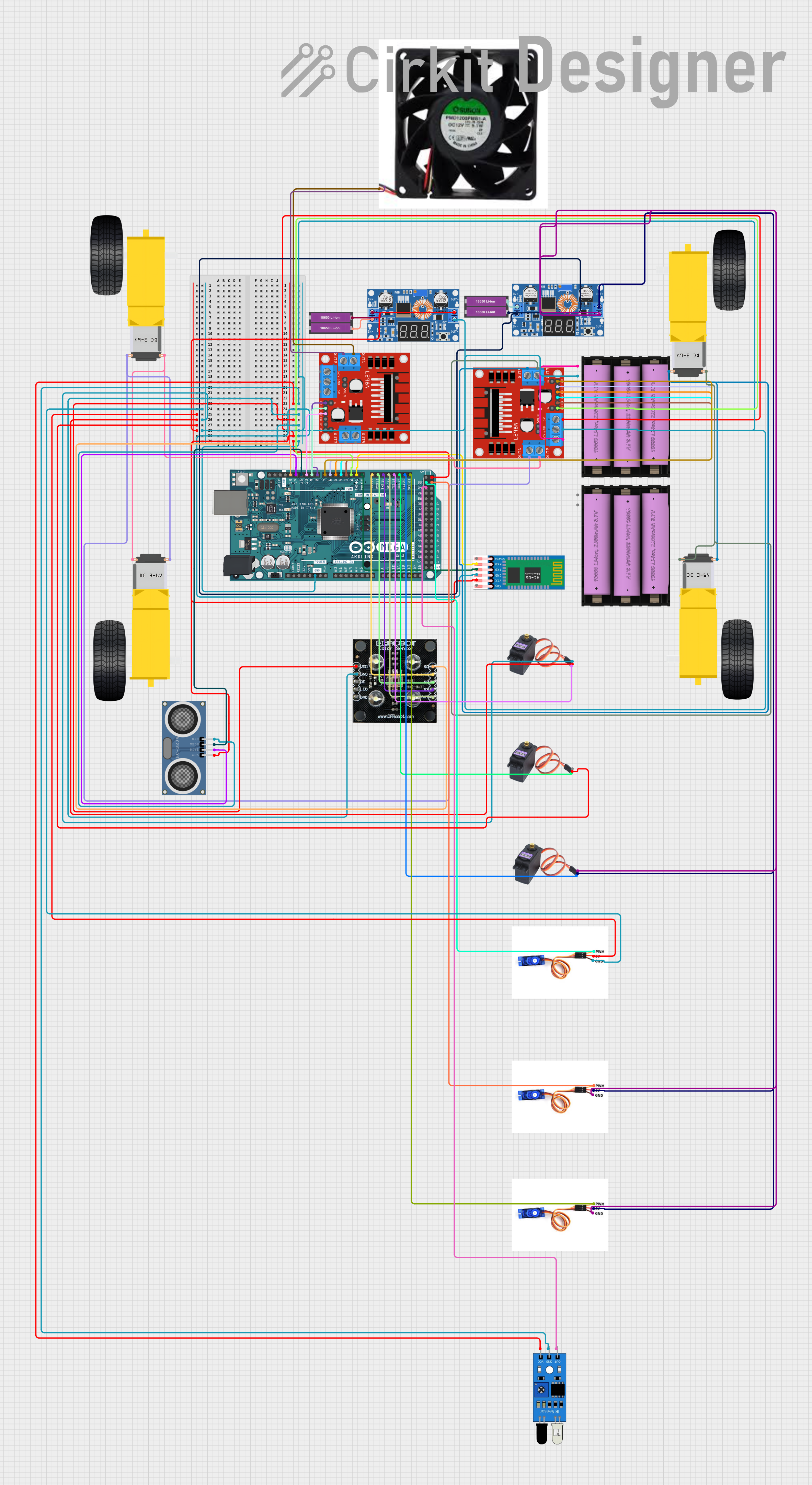
This circuit is designed to control a variety of components including motors, sensors, and a Bluetooth module, likely for a robotic or automated system. It is powered by 18650 Li-ion batteries, regulated by XL4015 DC-DC buck converters, and controlled by an Arduino Mega 2560 microcontroller. The circuit includes motor drivers for gearmotors, servos for precise control, sensors for distance measurement and color detection, and a Bluetooth module for wireless communication.
Component List
Power Sources
- 18650 Li-ion Battery x 2: Two sets of lithium-ion batteries providing the main power source for the circuit.
Voltage Regulators
- XL4015 5A DC Buck Step-down: Two step-down voltage regulators used to convert higher battery voltage to lower voltages required by various components.
Microcontrollers
- Arduino Mega 2560: A microcontroller board based on the ATmega2560, with numerous digital and analog I/O pins for interfacing with various components.
Communication Modules
- Hc 05: A Bluetooth module for wireless communication.
Motors and Motor Drivers
- Gearmotor DC Wheels (left and right): Four DC gearmotors used for driving wheels, likely in a robotic vehicle.
- MG996R: Three high-torque digital servos for precise movement control.
- SG90 servo motor: Three micro servos for smaller, precise movements.
- L298N DC motor driver: Two motor driver modules capable of driving up to four DC motors with full H-bridge control.
Sensors
- ir sensor: An infrared sensor for object detection or line tracking.
- HC-SR04 Ultrasonic Distance Sensor: An ultrasonic sensor for measuring distances to objects.
- RGB Colour Sensor: A sensor for detecting colors.
Actuators
- fan: A DC fan for cooling or airflow generation.
Wiring Details
Power Distribution
- 18650 Li-ion Battery x 2:
+to XL4015 Input+-to XL4015 Input-
Voltage Regulators
- XL4015 5A DC Buck Step-down:
- Output
+to 5V input of servos, motor drivers, and Arduino 5V pin. - Output
-to GND of servos, motor drivers, and Arduino GND pin.
- Output
Microcontrollers
- Arduino Mega 2560:
5VandGNDto various sensors and modules requiring 5V power.- Digital pins
D0toD13and others to control servos, motor drivers, sensors, and Bluetooth module.
Communication Modules
- Hc 05:
VCCto Arduino5VGNDto ArduinoGNDTXDto ArduinoD0 RX0RXDto ArduinoD1 TX0
Motors and Motor Drivers
Gearmotor DC Wheels (left and right):
- Connected to the outputs of L298N motor drivers.
MG996R and SG90 servo motor:
VCCto XL4015 Output+GNDto XL4015 Output-SIGto designated Arduino PWM pins.
L298N DC motor driver:
12Vto Set battery (7v)+GNDto Set battery (7v)-ENAandENBto Arduino PWM pins for speed control.IN1toIN4to Arduino digital pins for direction control.OUT1toOUT4to gearmotors and fan.
Sensors
ir sensor:
vccto Arduino5Vgndto ArduinoGNDoutto Arduino digital pin.
HC-SR04 Ultrasonic Distance Sensor:
VCCto Arduino5VGNDto ArduinoGNDTRIGandECHOto Arduino digital pins.
RGB Colour Sensor:
Vccto Arduino5VGNDto ArduinoGNDOUT,S0toS3to Arduino digital pins.
Actuators
- fan:
+to L298N motor driverOUT1-to L298N motor driverOUT2
Documented Code
Arduino Mega 2560 Code (sketch.ino)
void setup() {
  // put your setup code here, to run once:

}

void loop() {
  // put your main code here, to run repeatedly:

}
Additional Notes (documentation.txt)
No additional code documentation was provided.