
Arduino UNO Based Voltage Monitoring and Relay Control System
View and Edit Project In Cirkit Designer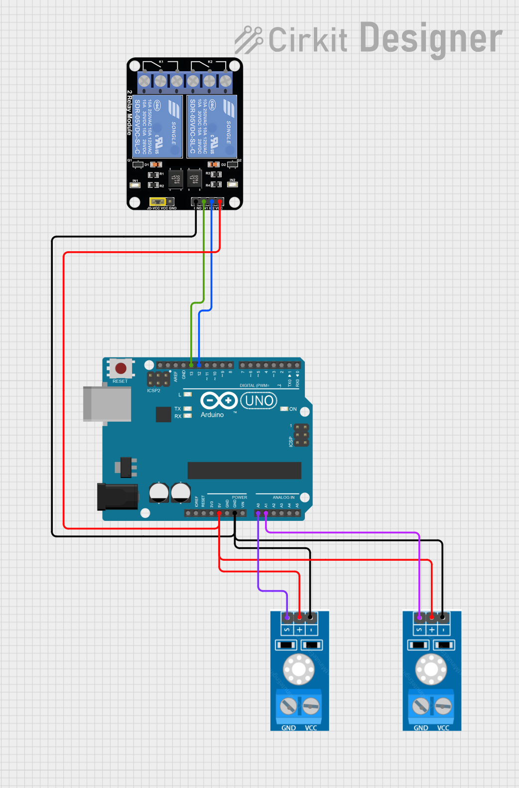
Circuit Documentation
Summary
The circuit in question consists of an Arduino UNO microcontroller, two identical voltage sensors, and a 2-channel relay module. The Arduino UNO serves as the central processing unit, interfacing with the voltage sensors to monitor voltage levels and controlling the relay module to switch external devices on or off. The voltage sensors are used to measure the voltage of an external source, and their outputs are connected to the analog inputs of the Arduino. The relay module is controlled by the digital outputs of the Arduino and can switch two separate circuits.
Component List
Arduino UNO
- Description: A microcontroller board based on the ATmega328P.
- Pins: UNUSED, IOREF, Reset, 3.3V, 5V, GND, Vin, A0-A5, SCL, SDA, AREF, D0-D13.
- Purpose: Acts as the central controller for the circuit, reading sensor data and controlling the relay module.
Relay Module 2 Channel
- Description: A module with two independent relay switches.
- Pins: GND, IN1, IN2, VCC, NC1, COM1, NO1, NC2, COM2, NO2.
- Purpose: Allows the Arduino to control high power devices, switching them on or off.
Voltage Sensor (2 units)
- Description: A module for measuring voltage in a circuit.
- Pins: GND, VCC, Output.
- Purpose: Measures the voltage of an external source and provides an output that can be read by the Arduino.
Wiring Details
Arduino UNO
- 5V: Connected to the VCC pins of both voltage sensors and the VCC pin of the relay module.
- GND: Connected to the GND pins of both voltage sensors and the GND pin of the relay module.
- A0: Connected to the Output pin of the first voltage sensor.
- A1: Connected to the Output pin of the second voltage sensor.
- D13: Connected to the IN1 pin of the relay module.
- D12: Connected to the IN2 pin of the relay module.
Relay Module 2 Channel
- VCC: Connected to the 5V pin of the Arduino UNO.
- GND: Connected to the GND pin of the Arduino UNO.
- IN1: Controlled by the D13 pin of the Arduino UNO.
- IN2: Controlled by the D12 pin of the Arduino UNO.
Voltage Sensor
- VCC: Connected to the 5V pin of the Arduino UNO.
- GND: Connected to the GND pin of the Arduino UNO.
- Output: Connected to either the A0 or A1 pin of the Arduino UNO (one sensor to A0, the other to A1).
Documented Code
Arduino UNO Code (sketch.ino)
void setup() {
  // put your setup code here, to run once:

}

void loop() {
  // put your main code here, to run repeatedly:

}
Note: The provided code is a template and does not contain any functional code to interact with the voltage sensors or the relay module. The user is expected to write the necessary code to read the voltage sensor outputs and control the relay module based on the application requirements.