Arduino-Controlled Automated Water Pump System with Level Sensing
Circuit Documentation
Summary of the Circuit
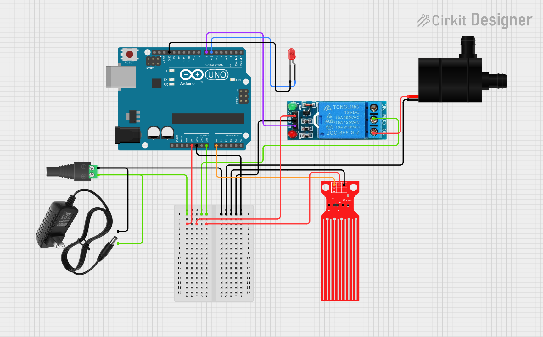
This circuit is designed to control a water pump based on the input from a water level sensor. It uses an Arduino UNO as the central microcontroller to process the sensor data and control the pump via a 12V single-channel relay. The circuit is powered by a 12V power supply, which is connected through a 2.1mm barrel jack with a terminal block. An LED indicator is included for visual feedback. The water level sensor monitors the water level, and when a certain threshold is reached, the Arduino UNO activates the relay, which in turn powers the water pump. The ground connections are shared among all components to complete the circuit.
Component List
Arduino UNO
- Microcontroller board based on the ATmega328P
- It has 14 digital input/output pins, 6 analog inputs, a 16 MHz quartz crystal, a USB connection, a power jack, an ICSP header, and a reset button.
12V Single Channel Relay
- An electromechanical switch used to control a high power circuit with a low power signal.
- It has a normally closed (NC), common (COM), and normally open (NO) terminal for switching, as well as an input (IN), ground (GND), and VCC for control.
Water Pump
- An electric pump for moving water.
- It has two terminals: VCC for power and GND for ground.
Water Level Sensor
- A sensor that detects the level of water in a tank or reservoir.
- It has a signal output (SIG), VCC, and GND.
2.1mm Barrel Jack with Terminal Block
- A connector for attaching external power supplies to the circuit.
- It has a positive (POS) and negative (NEG) terminal.
LED: Two Pin (red)
- A red light-emitting diode used as an indicator.
- It has an anode and a cathode.
12V Power Supply
- Provides the necessary power to the circuit.
- It has a positive (+) and negative (-) terminal.
Wiring Details
Arduino UNO
- Vin connected to the positive terminal of the 12V power supply.
- GND connected to the negative terminal of the 12V power supply.
- 5V output providing power to the Water Level Sensor and the 12V Single Channel Relay.
- A0 connected to the SIG pin of the Water Level Sensor for reading sensor data.
- D7 connected to the IN pin of the 12V Single Channel Relay for controlling the relay.
- D6 connected to the anode of the LED, with the cathode connected to GND for indicator purposes.
12V Single Channel Relay
- COM connected to the positive terminal of the 12V power supply.
- NO connected to the VCC of the Water Pump, allowing the pump to be powered when the relay is activated.
- IN controlled by the Arduino UNO's D7 pin.
- VCC connected to the 5V output from the Arduino UNO.
- GND connected to the common ground.
Water Pump
- VCC connected to the NO terminal of the 12V Single Channel Relay.
- GND connected to the common ground.
Water Level Sensor
- SIG connected to the A0 pin of the Arduino UNO for sensor data.
- VCC connected to the 5V output from the Arduino UNO.
- GND connected to the common ground.
2.1mm Barrel Jack with Terminal Block
- POS connected to the positive terminal of the 12V power supply.
- NEG connected to the negative terminal of the 12V power supply.
LED: Two Pin (red)
- Anode connected to the D6 pin of the Arduino UNO.
- Cathode connected to the common ground.
12V Power Supply
- Positive (+) terminal connected to the POS terminal of the 2.1mm Barrel Jack and the COM terminal of the 12V Single Channel Relay.
- Negative (-) terminal connected to the NEG terminal of the 2.1mm Barrel Jack and the common ground.
Documented Code
Arduino UNO - sketch.ino
void setup() {
  // put your setup code here, to run once:

}

void loop() {
  // put your main code here, to run repeatedly:

}
Note: The provided code is a template and does not contain any functional code to control the relay or read from the water level sensor. This will need to be implemented for the circuit to perform its intended function.