Raspberry Pi-Controlled LED Lighting System with Scheduled Color Changes
Circuit Documentation
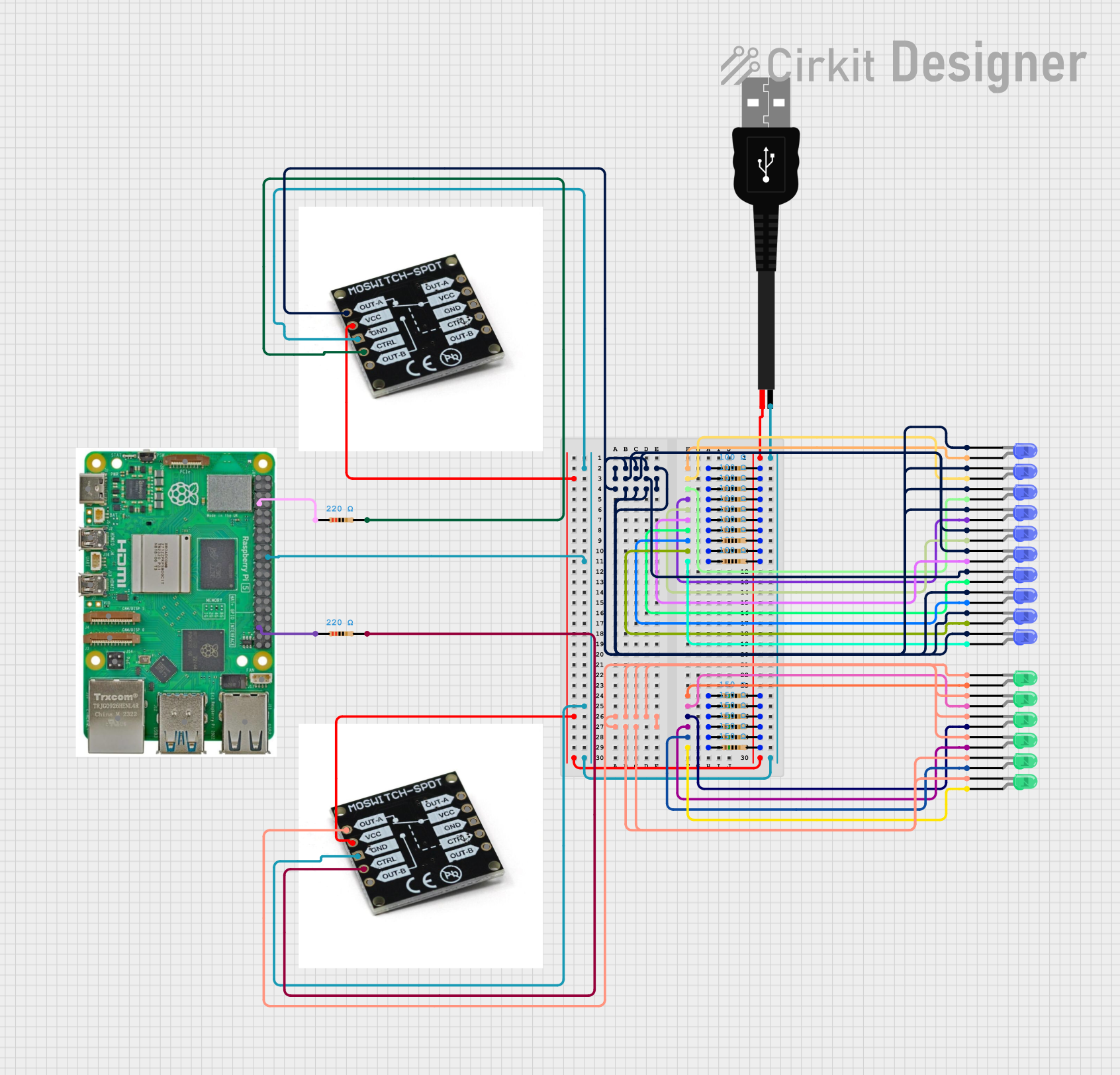
Summary
The circuit in question appears to be a control system utilizing a Raspberry Pi 5 microcontroller to manage a series of LEDs through MOSFET switches. The LEDs are divided into two groups, blue and green, each group being controlled by a separate MOSFET. The blue LEDs are scheduled to turn on and off at specific times, while the green LEDs are initially turned on and remain in that state. The circuit includes a series of resistors that are likely used for current limiting for the LEDs and for the proper operation of the MOSFETs.
Component List
Resistors
- 100 Ohm Resistors: Used for current limiting or voltage division.
- 150 Ohm Resistors: Used for current limiting or voltage division.
- 220 Ohm Resistors: Used for current limiting or voltage division.
LEDs
- Blue LEDs: Indicators or for visual signaling.
- Green LEDs: Indicators or for visual signaling.
MOSFET Switch SPDT
- MOSFET Switches: Used to control the power to the LEDs, allowing the Raspberry Pi to turn them on and off.
Raspberry Pi 5
- Microcontroller: The central controller of the circuit, capable of GPIO control, scheduling, and running the embedded code.
USB male 2 pin connection
- Power Connector: Provides power to the circuit.
Wiring Details
Resistors
- 100 Ohm Resistors: Connected to the anodes of blue LEDs and to a positive power source.
- 150 Ohm Resistors: Connected to the anodes of green LEDs and to a positive power source.
- 220 Ohm Resistors: Connected to the GPIO pins of the Raspberry Pi and to the control pins of the MOSFETs.
LEDs
- Blue LEDs: Cathodes are connected together and to the OUT-A pin of one MOSFET. Anodes are connected to 100 Ohm resistors.
- Green LEDs: Cathodes are connected together and to the OUT-A pin of another MOSFET. Anodes are connected to 150 Ohm resistors.
MOSFET Switch SPDT
- MOSFET Switches: VCC pins are connected to a positive power source. GND pins are connected to the ground. CTRL pins are connected to the Raspberry Pi GPIO pins through 220 Ohm resistors.
Raspberry Pi 5
- Microcontroller: GPIO pins are used to control the MOSFETs. Ground pin is connected to the ground.
USB male 2 pin connection
- Power Connector: Positive pin is connected to the VCC pins of the MOSFETs and the positive side of resistors. Negative pin is connected to the ground.
Documented Code
import RPi.GPIO as GPIO
import time
import logging
from datetime import datetime
import schedule
import atexit

# Configure logging
logging.basicConfig(level=logging.INFO, format="%(asctime)s - %(levelname)s - %(message)s")

class LEDController:
    def __init__(self, green_pin, blue_pin):
        self.green_pin = green_pin
        self.blue_pin = blue_pin
        self.setup_gpio()
        atexit.register(self.cleanup_gpio)  # Ensure cleanup on exit

    def setup_gpio(self):
        """Setup GPIO pins."""
        GPIO.setmode(GPIO.BCM)
        GPIO.setup(self.green_pin, GPIO.OUT)
        GPIO.setup(self.blue_pin, GPIO.OUT)
        GPIO.output(self.green_pin, GPIO.HIGH)  # Turn on green LEDs initially
        logging.info("GPIO setup complete. Green LEDs are on.")

    def control_led(self, pin, state):
        """Control LED state (on/off) for a specified pin, with error handling."""
        try:
            if GPIO.gpio_function(pin) == GPIO.OUT:
                GPIO.output(pin, GPIO.HIGH if state else GPIO.LOW)
                logging.info(f"{'Turned on' if state else 'Turned off'} LED on pin {pin}")
            else:
                logging.warning(f"Pin {pin} not set as output, unable to control LED.")
        except Exception as e:
            logging.error(f"Failed to control LED on pin {pin}: {e}")

    def cleanup_gpio(self):
        """Cleanup GPIO pins on exit."""
        GPIO.cleanup()
        logging.info("GPIO cleaned up.")

# Pin definitions and times
GREEN_LED_CTRL_PIN = 4
BLUE_LED_CTRL_PIN = 19
BLUE_LED_ON_TIME = "18:00"
BLUE_LED_OFF_TIME = "22:00"

def schedule_tasks(controller):
    """Schedule tasks for turning blue LEDs on and off."""
    schedule.every().day.at(BLUE_LED_ON_TIME).do(lambda: controller.control_led(controller.blue_pin, True))
    schedule.every().day.at(BLUE_LED_OFF_TIME).do(lambda: controller.control_led(controller.blue_pin, False))
    logging.info(f"Tasks scheduled: Blue LEDs on at {BLUE_LED_ON_TIME} and off at {BLUE_LED_OFF_TIME}.")

def main_loop():
    """Main loop to run scheduled tasks."""
    while True:
        schedule.run_pending()
        time.sleep(schedule.idle_seconds())

if __name__ == "__main__":
    try:
        led_controller = LEDController(GREEN_LED_CTRL_PIN, BLUE_LED_CTRL_PIN)
        schedule_tasks(led_controller)
        main_loop()
    except KeyboardInterrupt:
        logging.info("Program interrupted by user.")
    except Exception as e:
        logging.error(f"Unexpected error: {e}")
This code is designed to run on a Raspberry Pi 5 and controls a set of LEDs. It sets up the GPIO pins, schedules tasks for turning the blue LEDs on and off at specified times, and contains a main loop to run these scheduled tasks. The green LEDs are turned on at the start and remain on. The code includes error handling and logging for debugging purposes.